
Corrosion resistant pressure transducer

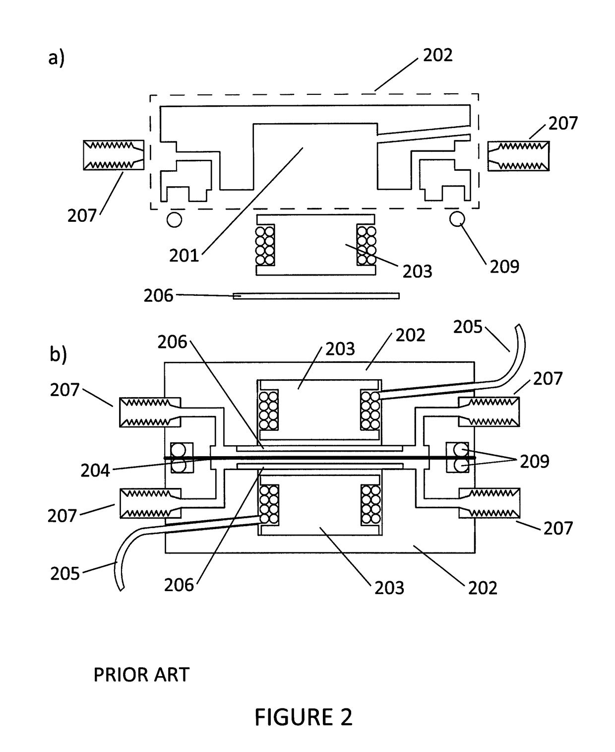
a pressure transducer and corrosion resistance technology, applied in the direction of fluid pressure measurement using inductance variation, pressure difference measurement between multiple valves, instruments, etc., can solve the problems of high cost, critical and expensive components of differential viscometers, and the wet surface of the transducer is prone to corrosion, and the element is also susceptible to corrosion

Inactive Publication Date: 2017-05-02
WYATT TECH
View PDF16 Cites 1 Cited by
  • Summary
  • Abstract
  • Description
  • Claims
  • Application Information

AI Technical Summary

Benefits of technology

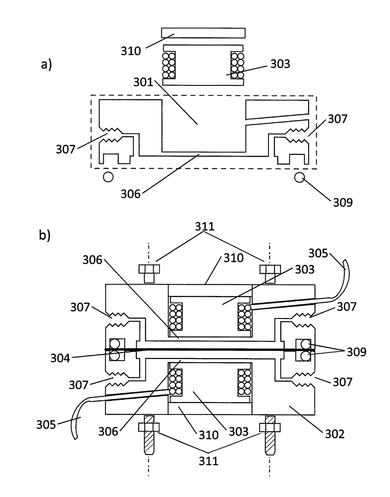
The patent describes a new pressure transducer sensor design that is simpler and more accurate than previous methods. The sensor is made by milling a cavity into a block of stainless steel and then holding the pickup coils in place with epoxy cement. The sensor is exposed to sample or reference fluids through a single solid surface, reducing the likelihood of leakage and making it easier to connect fluid fitting connections. In some embodiments, the pickup coil is wound on a nickel superalloy frame, improving sensitivity. The membrane is protected from corrosion by coating or encapsulation in a soft, non-magnetic material like Teflon. The design also allows for a wider variety of materials to be used for the membrane.

Problems solved by technology

A critical, and expensive, component of differential viscometers is the pressure transducer.
As sample fluids flow through the transducer, its wetted surfaces are prone to corrosion due to exposure to the sample solvent.
This element is also susceptible to corrosion.

Method used


Image

  • Corrosion resistant pressure transducer
  • Corrosion resistant pressure transducer
  • Corrosion resistant pressure transducer

Examples


Embodiment Construction

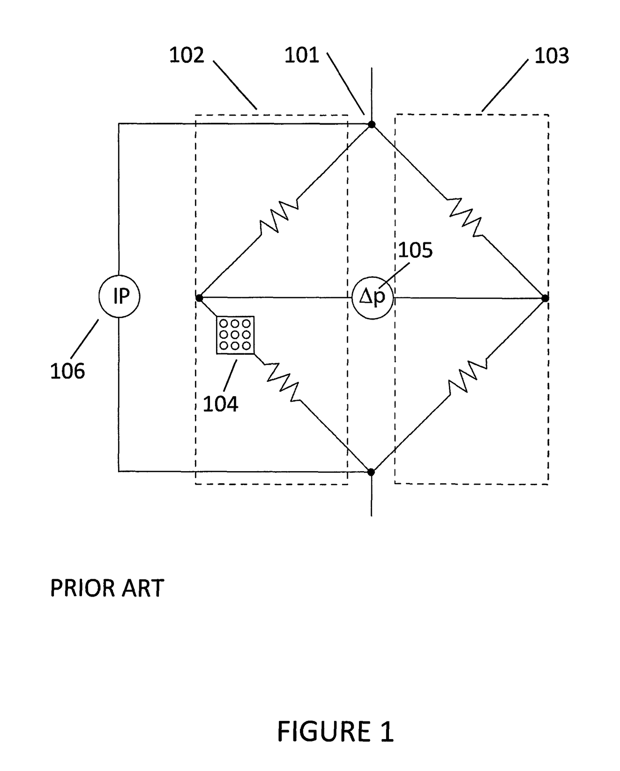
[0008]Most viscometers for use with high performance liquid chromatography (HPLC) systems utilize a capillary bridge design, as shown in FIG. 1. The fluid stream splits at the top of the bridge 101, and half of the sample flows through each bridge arm 102 and 103. Since the bridge is symmetric, the differential pressure transducer in the center of the bridge measures zero when all four arms are filled with solvent. When a sample is injected it flows into both arms. One arm of the bridge 102 contains an additional delay volume 104 so that the sample enters the delay volume 104, but the pure solvent that was present prior to sample injection exits, causing a pressure imbalance in the bridge which is measured by a pressure transducer 105 in the center of the bridge. This imbalance pressure, combined with the inlet pressure measured by a separate pressure transducer 106 between the top and bottom of the bridge, gives the specific viscosity through the relation

[0009]ηsp=ηη0-1=4⁢Δ⁢⁢pIP-2⁢...


PUM

PropertyMeasurementUnit
pressureaaaaaaaaaa
corrosiveaaaaaaaaaa
physical propertiesaaaaaaaaaa

Abstract

A pressure transducer is disclosed wherein no wetted areas have been welded. A cavity is milled into the back of each of the blocks of a material which will make up the body of the transducer. Pickup coils are placed into these cavities and are held in place generally with epoxy cement. With the coils mounted within the sensor body, the surface which will be exposed to the sample or reference fluids is comprised of a single, solid material with no welding joints. Further, as the sensor block half is made of a single, solid material, fluid fitting connections may be machined directly into the body. The pickup coil placed within the improved sensor body may be wound on an open frame of nickel superalloy (NiSA). Another embodiment involves coating or encapsulating the sensing membrane within a soft, non-magnetic material protecting it from corrosion.

Description

BACKGROUND[0001]Viscometry is a widely used measurement method to help determine the physical properties of particles and molecules in solution. Generally used in conjunction with size exclusion chromatography (SEC), also known as high performance liquid chromatography (HPLC), these instruments measure the differential viscosity between a sample bearing solution and a reference liquid, and are hence referred to as differential viscometers. The specific viscosity of the sample may then be determined, and from this value, and knowledge of the sample concentration, the intrinsic viscosity of the sample may be derived. When viscometric and concentration measurements are further coupled with multi-angle light scattering measurements, further information regarding molecular conformation and molecular interactions may be determined.[0002]A critical, and expensive, component of differential viscometers is the pressure transducer. As sample fluids flow through the transducer, its wetted surf...

Claims


Application Information

Patent Timeline
Patent Type & Authority Patents(United States)
IPC IPC(8): G01L9/14G01L13/02G01L9/10G01L19/06G01N11/08G01L13/06G01L9/00G01D5/12
CPCG01D5/12G01L9/007G01L13/025G01L19/0654G01N11/08
Inventor TRAINOFF, STEVEN P.
Owner WYATT TECH
Learn More