Combination of cylinder and piston ring

a technology of piston rings and cylinders, which is applied in the direction of superimposed coating processes, machines/engines, mechanical apparatuses, etc., can solve the problems of low adhesion to substrates, failure to withstand a long time of use, and local peeling of coatings, etc., and achieve excellent wear resistance

Inactive Publication Date: 2017-05-09
RIKEN CO LTD
View PDF32 Cites 3 Cited by
  • Summary
  • Abstract
  • Description
  • Claims
  • Application Information

AI Technical Summary

Benefits of technology

[0007]An object of the present invention is to provide a combination of a cylinder made of a hypereutectic Al—Si alloy and a piston ring comprising a hard carbon coating on an outer peripheral surface, both exhibiting excellent wear resistance.SUMMARY OF THE INVENTION
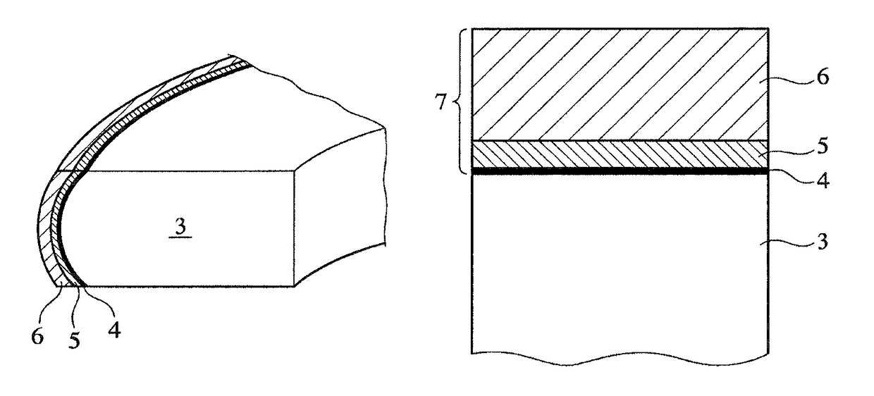
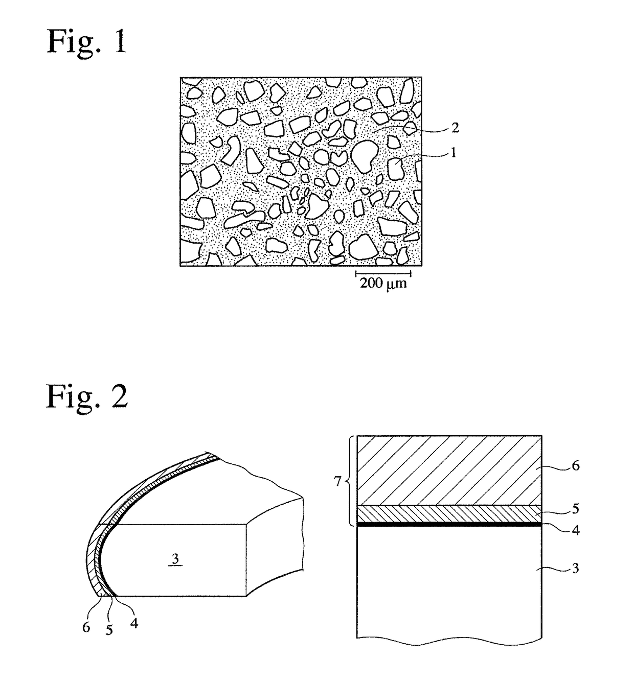
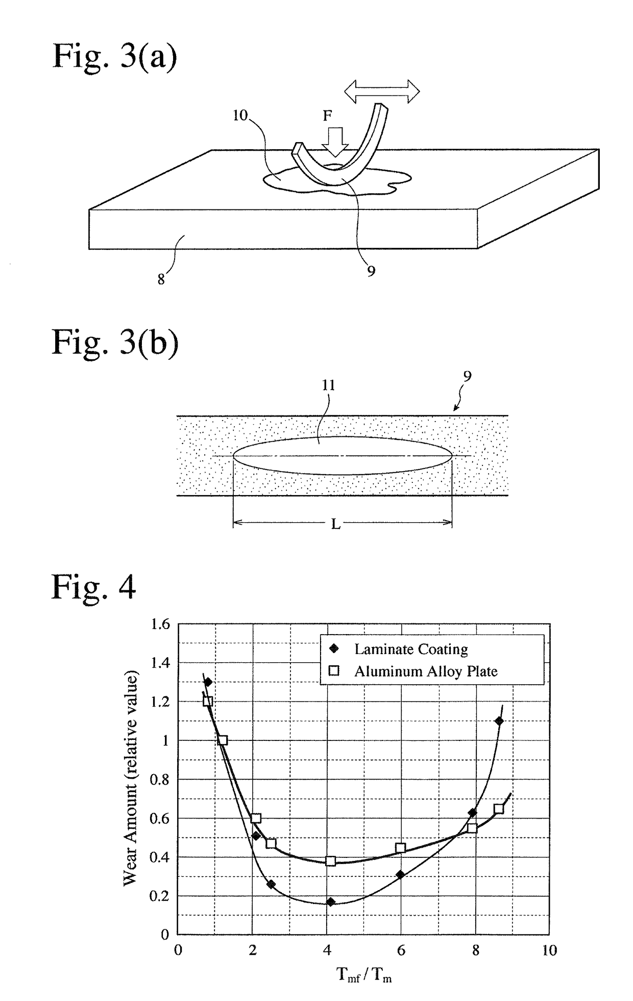
[0008]As a result of intensive research on the coating formed on the piston ring of Patent Reference 1, the inventors have found that by reducing residual stress in the outermost metal-free DLC layer, namely, by reducing the hardness and modulus of the metal-free DLC layer to as low as those of Si particles in an hypereutectic Al—Si alloy, while suppressing increase in plastic deformability, and by increasing a thickness ratio of the metal-free DLC layer to the metal-containing DLC layer, a combination of the cylinder and the piston ring can exhibit excellent wear resistance even when the cylinder is made of a hypereutectic Al—Si alloy.

Problems solved by technology

However, the practical use of hard carbon coatings have been largely hindered by their two essential properties that large residual stress exists because of their forming process, and that carbon bonds are chemically stable, resulting in low adhesion to substrates.
However, when boundary lubrication occurs particularly in an early stage of operation of an engine with a hypereutectic Al—Si alloy as a mating member, detached Si particles act as abrasives, likely causing the local peeling of a coating due to increased local stress, failing to withstand a long period of use.

Method used


Image

  • Combination of cylinder and piston ring
  • Combination of cylinder and piston ring
  • Combination of cylinder and piston ring

Examples


example 1

[0030]50 degreased piston rings each having a rectangular cross section and a barrel-faced outer peripheral surface and made of nitrided SUS420J2 [nominal diameter (d): 90 mm, thickness (h1): 1.2 mm, and width (a1): 3.2 mm] were stacked on a coating jig, and the coating jig was placed on a rotating table in a film-forming apparatus comprising a first target of Cr and a second target of W. Composition-analyzing samples of hardened, mirror-polished SKH51 having an outer diameter of 25 mm and a thickness of 5 mm were set on a similar jig to the jig for the outer peripheral surfaces of piston rings. After the apparatus was evacuated to a predetermined degree of vacuum, negative bias voltage was applied to the coating jig while introducing an Ar gas, to carry out a cleaning treatment by glow discharge. Thereafter, a Cr layer was formed on the outer peripheral surface of each piston ring for a predetermined period of time by the sputtering of Cr. After stopping the sputtering of Cr, an C2...

examples 6-8

[0049]Laminate coatings were formed on the piston rings and the composition-analyzing samples in the same manner as in Example 1, except that Cr / DLC(Cr) / DLC was formed in Example 6 by using metallic Cr for the first and second targets, and that Ti / DLC(Ti) / DLC and W / DLC(W) / DLC were formed in Examples 7 and 8 by using Ti and W, respectively, in place of Cr of Example 6. In Examples 7 and 8, after stopping the sputtering of Ti and W, a N2 gas was introduced together with an Ar gas and an C2H2 gas. Because of an increased amount of metal ions due to the targets 2 times as large as in Example 1, the sputtering power was lowered, and the time period of forming each layer was adjusted, such that Tmf / Tm was in a predetermined range. The measurement results are shown in Tables 3 and 4. Excellent wear resistance was obtained in any Examples.

[0050]

TABLE 3MetalLayerMetal-Containing DLC LayerT(1)MetalHydrogenTm(2)No.Type(μm)TypeAtomic %(atomic %)(μm)Example 6Cr0.59Cr25.821.32.24Example 7Ti0.35Ti...


PUM

PropertyMeasurementUnit
thickaaaaaaaaaa
diametersaaaaaaaaaa
Young's modulusaaaaaaaaaa

Abstract

To provide a combination of a cylinder made of a hypereutectic Al—Si alloy and a hard-carbon-coated piston ring both exhibiting excellent wear resistance, the piston ring is provided with a laminate coating at least on an outer peripheral sliding surface thereof; the laminate coating comprising a metal layer, a metal-containing, hard carbon layer, and a metal-free, hard carbon layer in this order from the substrate side; the laminate coating having Martens' hardness (indentation hardness) HMs of 5-13 GPa, indentation modulus E of 70-200 GPa, and a deformation ratio Rpe of 0.45 or less, which is expressed by a ratio (Wp / We) of plastic deformation energy Wp to elastic deformation energy We; and a ratio (Tmf / Tm) of the thickness Tmf of the metal-free, hard carbon layer to the thickness Tm of the metal-containing, hard carbon layer being 2-8.

Description

FIELD OF THE INVENTION[0001]The present invention relates to a combination of a cylinder and a piston ring sliding on an inner surface of the cylinder, which is used for internal combustion engines.BACKGROUND OF THE INVENTION[0002]Internal combustion engines such as automobile engines are recently strongly demanded to have improved fuel efficiency. Accordingly, research and development have been widely carried out to achieve size reduction, weight reduction, friction loss decrease, etc. For example, attempts have been made to use aluminum alloys for cylinders, and to coat piston rings with low-friction-coefficient, hard carbon called diamond like carbon (DLC).[0003]Though some aluminum alloy cylinders have portions in direct sliding contact with piston rings, which have insert-molded cast iron liners or plating, both requirements of cooling performance and cost on cylinders have demanded to use for cylinders aluminum alloys having excellent wear resistance, for example, a hypereutec...

Claims


Application Information

Patent Timeline
Patent Type & Authority Patents(United States)
IPC IPC(8): F16J9/26C23C16/02F02F1/18C23C28/02F02F1/00C23C16/26F02F5/00
CPCF16J9/26C23C16/0272C23C16/26C23C28/021C23C28/027F02F1/00F02F1/18F02F5/00F05C2203/0882F05C2251/10
Inventor KUNIMOTO, AKIRAMORONUKI, MASAKI
Owner RIKEN CO LTD
Why Eureka
Try Eureka