Argon production method and apparatus

a technology of argon and production method, applied in the direction of liquefaction, lighting and heating apparatus, separation processes, etc., can solve the problems of increasing the height of the argon cylinder, increasing the argon cylinder volume, so as to reduce the overall coldbox space, reduce the associated size of equipment/vessels, and reduce the cos

Active Publication Date: 2017-05-09
PRAXAIR TECH INC
View PDF38 Cites 0 Cited by
  • Summary
  • Abstract
  • Description
  • Claims
  • Application Information

AI Technical Summary

Benefits of technology

[0009]The adsorbent can be a molecular sieve and the alternating cycle can be a temperature swing adsorption process. In such case, the regeneration gas is a heated regeneration gas stream and the adsorbent bed is warmed to desorb adsorbed oxygen by terminating indirect heat exchange between the adsorbent bed and the coolant stream and passing the heated regeneration gas stream into the adsorbent bed. Prior to refilling the adsorbent bed with the purified argon liquid, the indirect heat exchange between the adsorbent bed and the coolant stream is resumed. A nitrogen-rich vapor column overhead stream, composed of nitrogen-rich vapor, can be removed from either the low pressure column or the high pressure column of the cryogenic air separation plant and at least partially warmed in a main heat exchanger of the cryogenic air separation plant to help cool a compressed and purified air stream composed of the air to be separated within the cryogenic air separation plant. The regeneration gas can be formed from part of the nitrogen-rich vapor column overhead stream after having been at least partially warmed the main heat exchanger. During the on-line periods of the alternating cycle, a subsidiary liquid argon stream is produced that contains a further part of the liquid argon and the subsidiary liquid argon stream is introduced into a storage tank to store the further part of the liquid argon. A displacement gas stream is generated by removing a subsidiary liquid argon stream from the storage tank and vaporizing the subsidiary liquid argon stream and the displacement gas stream is introduced into the adsorbent bed to assist in motivating the residual liquid argon stream from the adsorbent bed to the cryogenic air separation plant.
[0015]The subjection invention possesses several advantages relative to current and proposed argon refining processes. In contrast to the current “superstaged” distillation approach to argon refining, the use of a hybrid-liquid adsorption system will drastically reduce overall coldbox space. Relative to past liquid phase argon adsorption processing arrangements of the prior art, the regeneration gas / liquids are effectively recovered by utilizing the existing cryogenic distillation infrastructure. This is a critical element of economic viability since foregoing the value of the liquid argon contained in the vessels is critical to economic operation. Relative to prior art gas adsorption processes feed gas compression is not required. In addition, by processing liquid argon directly, the associated size of the equipment / vessels is drastically reduced. The present invention therefore provides an inherent cost and operating expense benefits over the prior art.

Problems solved by technology

However, such systems will typically attain column / coldbox heights in excess of 200+ ft.
As a consequence, considerable expense is incurred to attain high purity (split columns, multiple coldbox sections, liquid reflux / return pumps).
This situation is further compounded for large air separation plants where column feed / draw re-distribution points typically consume more height.
There exists a need to drastically shorten the argon distillation column without returning to the use of catalytic combustion (and its associated complexity and operating costs).
Since distillation cost is proportional to the logarithm of purity a substantial cost (and height) is incurred in attaining 1 ppm O2 in argon.
The use of a reducing gas makes it difficult to integrate the adsorbent beds with the air separation plants in that the reducing gas is not made in the air separation plant, but must be on hand to regenerate the adsorbents.
More importantly, during regeneration of the adsorbent, argon rich fluids will be lost from the process.
The problem with this type of integration is that it requires the inclusion of a crude argon compressor (and associated power consumption).
The problem with this type of integration is that the vapor must be re-liquefied resulting in increased power consumption.

Method used


Image

  • Argon production method and apparatus
  • Argon production method and apparatus

Examples


Embodiment Construction

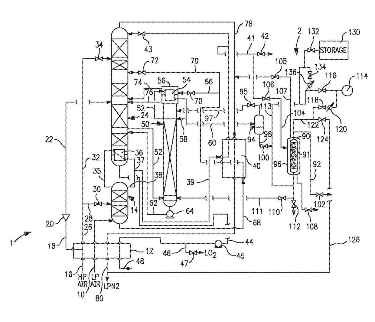
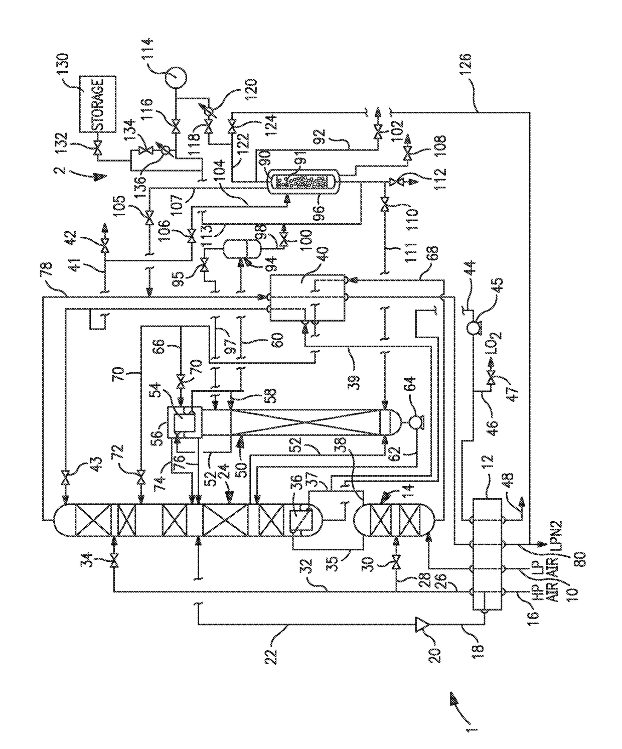
[0017]In reference to FIG. 1, an air separation plant 1 is illustrated that is integrated with an argon purification system 2. The subject equipment is typically enclosed in an insulated enclosure (or coldbox—not shown). Incoming air by way of a compressed and pre-purified feed air stream 10 is separated into oxygen and nitrogen-rich fractions in high and low pressure distillation columns 14 and 24. Argon is separated in an argon column 50 to produce liquid argon having oxygen impurities. An impure liquid argon stream 60 composed of part of the liquid argon produced in the argon column 50 is purified in the argon purification system 2 to produce a purified liquid argon product 92.

[0018]It should be noted that high and low pressure distillation columns 14 and 24 and argon column 50 represent distillation columns in which vapor and liquid are counter-currently contacted in order to affect a gas / liquid mass-transfer based separation of the respective feed streams. Columns 14, 24 and 50...


PUM

PropertyMeasurementUnit
temperatureaaaaaaaaaa

Abstract

A method and apparatus for producing a purified liquid argon product in which liquid argon having oxygen impurities is produced in a cryogenic air separation plant by separating argon from oxygen within an argon column. An impure liquid argon stream, composed of part of the liquid argon, is purified in an adsorbent bed by adsorbing the oxygen impurities in an adsorbent to produce a purified liquid argon stream that constitutes the purified liquid argon product. During adsorption, the adsorbent bed is maintained at a reduced temperature with a coolant to prevent vaporization of the liquid argon. The bed is then regenerated by draining residual liquid argon from the adsorbent bed, introducing the residual liquid argon back into the air separation plant and then desorbing the oxygen impurities with a regeneration gas. After regeneration, the adsorbent bed is refilled with purified liquid argon prior to being brought back on-line.

Description

RELATED APPLICATION[0001]This application claims the benefit of U.S. Provisional Application Ser. No. 61 / 771,468, filed on Mar. 1, 2013, which is incorporated herein by reference.FIELD OF THE INVENTION[0002]The present invention relates to a method and apparatus for producing argon in which argon is separated from air within a cryogenic air separation plant having an argon column. A liquid argon stream is produced from the air separation plant subsequently purified by removing oxygen impurities within an adsorbent bed. More particularly, the present invention relates to such a method and apparatus in which the adsorbent bed is operated in accordance with a temperature swing adsorption process in which the adsorbent bed is maintained at a reduced temperature that is sufficient to prevent vaporization of the liquid argon stream through indirect heat exchange with a coolant and during regeneration of the adsorbent bed, residual liquid argon contained in the adsorbent bed is introduced ...

Claims


Application Information

Patent Timeline
Patent Type & Authority Patents(United States)
IPC IPC(8): F25J3/00B01D53/04C01B23/00F25J3/04
CPCF25J3/04733B01D53/04C01B23/0052C01B23/0057F25J3/0409F25J3/04303F25J3/04412F25J3/04678B01D2253/108B01D2256/18B01D2257/104C01B2210/0034C01B2210/0045F25J2205/02F25J2205/60F25J2205/66F25J2245/42C01B2210/0014F25J2215/58F25J2220/04
Inventor HOWARD, HENRY E.KECHAGIA, PERSEFONI E.BARRETT, PHILIP A.HANDLEY, JAMES R.
Owner PRAXAIR TECH INC
Why Eureka
Try Eureka