Eureka AIR delivers breakthrough ideas for toughest innovation challenges, trusted by R&D personnel around the world.

System and method for hydrothermal reaction

a hydrothermal reaction and hydrothermal technology, applied in the direction of pressurized chemical processes, transportation and packaging, supercritical conditions, etc., can solve the problems of high cost and maintenance difficulties, unsafe reaction systems, and limited heating area, so as to improve the capacity of pressure bearings and avoid maintenance difficulties , the effect of greatly improving the reliability of the whole pressure system

Active Publication Date: 2017-05-30
TONGJI UNIV
View PDF21 Cites 2 Cited by
  • Summary
  • Abstract
  • Description
  • Claims
  • Application Information

AI Technical Summary

Benefits of technology

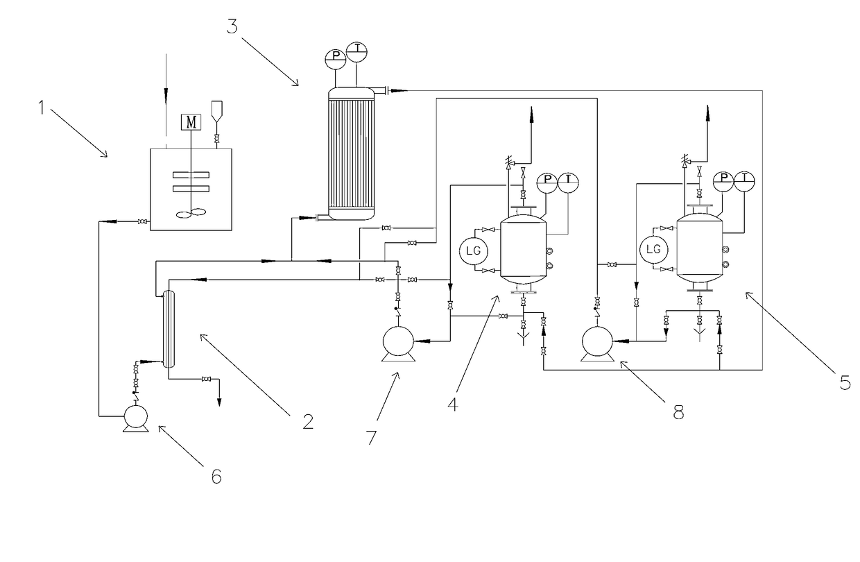
[0012]By adopting the system or method for the hydrothermal reaction in the present invention, the heating and reaction procedures can be separated in the hydrothermal reaction, because heating the container, i.e. the reactor itself is not required, which thus avoids the safety problems brought by the reactor heating and reduces the manufacture cost of the reactor.
[0016]The system provided by the present invention can further include a heat exchanger that in communication with outlet of the container via pipes. The heat exchanger includes a heat exchanger component such as a sheath tube heat exchanger, a spiral plate heat exchanger or a shell and tube heat exchanger, preferably, a sheath tube heat exchanger. The heat exchanger is used for transferring the heat of the fluid that is discharged out of the outlet of the container, i.e. the fluid after the hydrothermal reaction, to other fluid that needs to be heated, for example, fluid that flows before the heater, i.e. the fluid before heating or the water before the reaction. In this way, a certain amount of heat can be saved and the reacted fluid can be cooled down quickly, avoiding the solid-liquid separation of the material during the transportation process, and thus benefiting being discharged directly or being further processed, ensuring the system stay unblocked and stable. The method provided by the present invention can further include: the fluid after the hydrothermal reaction is made to flow across the heat exchanger as noted here.
[0020]Compared with the batch processing reactor adopting the large-scale dividing wall type heating surface, the present invention adopts a tubular heater, or a spiral plate heater, or sheath tube heater, and adopts the pumping way to make the fluid that contains the particulate matters flow (such as the mixed materials of fly ash and water) to be mixed completely without the need of stirring. The fluid containing particulate matters circulates while being heated in the pipe or in the spiral plate, avoiding the sealing design as required by the stirring apparatus, avoiding the maintenance difficulties due to the possible scale formation on the wall of the salt precipitation. Especially, when compared with the volume type reaction tank, the pressure bearing capability is greatly improved in terms of the tube heating surface or the spiral plate heating surface. However, the heat preserving container with larger volume in the system does not play the role of heating, and the continuous turnover and circulating of the material avoids the need that the stirrer must stir the material evenly, therefore the reliability of the whole pressure system is greatly enhanced.

Problems solved by technology

Although the present technology adopts a plurality of parallel pressure container reactors to realize continuity or semi-continuity of the hydrothermal reaction, the container as the reactor is also a heater at the same time, which makes the reaction system unsafe.
However, when the present technology is applied in the engineering design and operations, the present implementation apparatus, i.e. the large-scale tank batch reactor, needs to perform both heating and heat preserving to the material, which leads to high cost and maintenance difficulties.
However, the reactor is integrated with both heating and reacting, thus leading to the defects in being large-scale and safety, for example: the requirement of the manufacturing material is high, and on the one hand, the large-scale high pressure tank, i.e. the reactor, itself as a heating surface is unsafe; on the other hand, the heating area is limited, and the slow heating rate affects the reaction velocity, reducing the efficiency of the system.
The magnetic stirring is commonly used in the present large-scale high pressure tank, when the temperature is increasing, the cooling system is needed for preventing magnetism loss, such that the system is complicated.

Method used


Image

  • System and method for hydrothermal reaction
  • System and method for hydrothermal reaction
  • System and method for hydrothermal reaction

Examples


embodiment 1

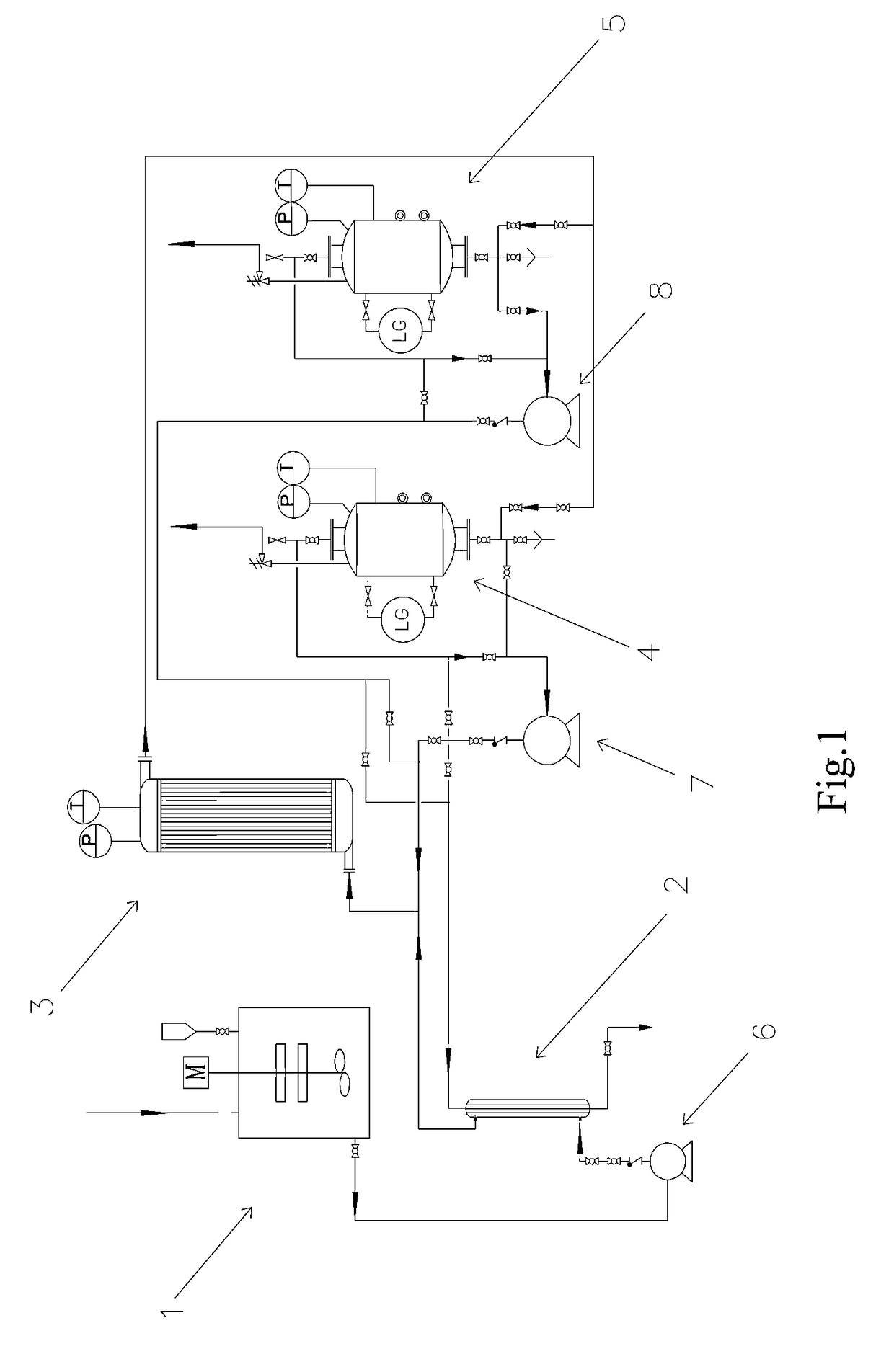
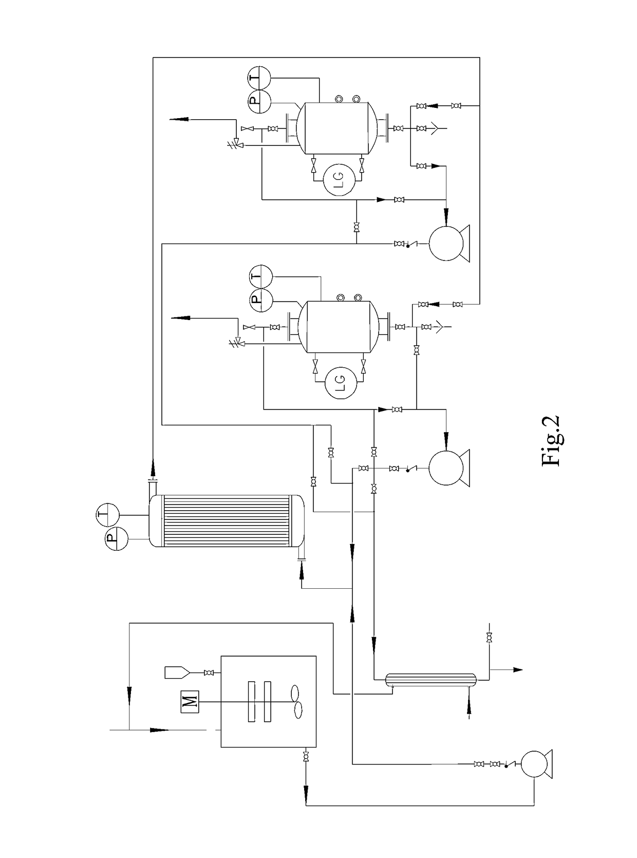
[0048]The present embodiment adopts the system as shown in FIG. 2, in which the heater is changed to a serpentuator heater.

[0049]The fly ash generated by a 1000 t / d waste incineration plant contains dioxin, heavy metal and high salt concentration, especially Cl ion. When processed with technique of the present invention, it is firstly washed by clean water, separating the stones and sediments, and then the washed fly ash enters into the stock tank through the material feeder. The water that is used for making the grout is preheated by the heat exchanger and then transported to the stock tank, becoming the grout after mixing with the fly ash. The heat source of the heat exchanger is the material of the heat preserving container. Similar to the solube ferrite and ferric salt in the solid form pass through the material feeder and then into the stock tank, starting the stirrer and stirring even as disclosed in the PCT / CN2011 / 073562. The grout is transported to the heater by the feeding ...

embodiment 2

[0050]The present embodiment adopts the system in FIG. 2.

[0051]A medical waste incinerator fly ash disposal station is established between two cities, for processing the medical waste incineration fly ash totals about 2.8 to 3 t / d that is generated by the two cities. The medical waste incineration fly ash includes dioxin, heavy metal and high salt concentration, especially Cl—, when processed with the technology of the present invention, the fly ash together with any of the solube ferrite and ferric salt disclosed in the PCT / CN2011 / 073562, preferably ferric salt, are mixed according to measurement and then pass through the material feeder and enters into the stock tank. The water for making the grout runs through the heat exchanger and transported to the stock tank after being preheated; the heat source of the heat exchanger is the material of the heat preserving container. Start the stirrer and stir the water and the fly ash to be mixed into grout, and then add another kind of ferr...

embodiment 3

[0052]The present embodiment adopts the system in FIG. 3. The volume of the first heat preserving container, the second heat preserving container and the heat preserving container is all 5 m3, which is the same as the system adopted by the first embodiment.

[0053]The fly ash generated by a 1500 t / d waste incineration plant contains dioxin, heavy metal and high salt concentration, especially Cl ion.

[0054]When the first heat preserving container preserve the heat after reaching to the predetermined temperature in order to keep the temperature for a given reaction time such as 60 min, close the first feedstock loop, the first circulation loop and the first discharging loop; at this time, start the feeding pump and feed the material to the heater, and then to the second heat preserving container, after that, the material is circulating between the second heat preserving container and the heater; when the second heat preserving container reaches to the predetermined reaction time and disc...


PUM

PropertyMeasurementUnit
sizeaaaaaaaaaa
lengthaaaaaaaaaa
temperatureaaaaaaaaaa

Abstract

A system for hydrothermal reaction comprises a heater (3) including a circulating component for fluid flowing across and a heat source for heating fluid, and a reactor (4, 5) including a heat preserving container in communication with the circulating component via pipes. A method for hydrothermal reaction comprises heating the fluid including the reactant and water for hydrothermal reaction, and feeding the heated fluid to the heat preserving container to perform the hydrothermal reaction.

Description

CROSS-REFERENCE TO RELATED APPLICATION[0001]This application is a national stage application of International Application No. PCT / CN2012 / 70982, now WO 2013 / 11700, filed on Feb. 9, 2012, the disclosure of which are fully incorporated herein by reference.FIELD OF THE INVENTION[0002]The present invention belongs to the field of hazard-free treatment and recycling treatment of solid waste. Specifically, the present invention relates to a system for hydrothermal reaction, and particularly relates to hydrothermal reaction for hazard-free treatment and recycling treatment of solid waste such as incineration fly ash, sludge, biomass waste, etc., and especially to continuous and semi-continuous hydrothermal reaction. The present invention also relates to the method for the hydrothermal reaction.DESCRIPTION OF THE PRIOR ART[0003]Hydrothermal reactions are the reaction of a reactant under a certain temperature and pressure after being mixed with water, which is an important reaction pattern of...

Claims


Application Information

Patent Timeline
Patent Type & Authority Patents(United States)
IPC IPC(8): B01J3/00B01J8/00B01J3/04B01J6/00B01J19/00C10L9/08C10L9/00B09B3/00C10G1/06C10G1/00B01J19/24B01J19/02
CPCB01J8/00B01J3/008B01J3/04B01J6/00B01J19/0013B01J19/02B01J19/2445B09B3/0083C10G1/008C10G1/065C10L9/086B01J2219/0009B01J2219/0011B01J2219/00063B01J2219/00065B01J2219/00092B01J2219/00105B01J2219/00114B01J2219/0286B09B3/40
Inventor CHEN, DEZHENMA, XIAOBOYIN, LIJIEQIU, LIN
Owner TONGJI UNIV
Why Eureka
Eureka Blog
Learn More