Long-range surface-insensitive passive RFID tag

Active Publication Date: 2017-05-30
ANTENNASYS
View PDF10 Cites 1 Cited by
  • Summary
  • Abstract
  • Description
  • Claims
  • Application Information

AI Technical Summary

Benefits of technology

[0023]One or more embodiments described in the specification are related to a long-range surface-insensitive passive RFID tag. Embodiments of the invention may use an electrically small, magnetic mode antenna oriented with the circulating RF current flowing in a plane perpendicular to the mounting surface. One or more embodiments may provide an inexpensive and effective mechanism to separately adjust both resonance and impedance matching by moving the position of a resonating capacitor and the position of an RFID chip along a slot in the antenna conductor. One or more embodiments may use an air-core structure for the lowest losses and lowest cost. One or more embodiments may enable metal-on-metal operation, for example for tracking equipment, and operation on a human body surface, for example

Problems solved by technology

There are several issues when tagging people including conductivity of the human body, RF blockage from the human body and methods of attaching the tag such that it is acceptable to the person while remaining effective.
These issues may reduce the range over which the tag may be interrogated when compared the more benign environs of a cardboard box.
Since the RFID chip itself is very small, the limiting factor for the total physical size is generally the antenna.
Thus, the cost of size reduction is some combination of a reduced bandwidth and loss of efficiency.
If the resultant bandwidth is too narrow, it may not have acceptable performance over the desired band of operation.
Therefore, bandwidth of the antenna is a relevant limiting factor in tag performance.
It is manifested as signal loss in the antenna due to losses in the antenna struc

Method used


Image

  • Long-range surface-insensitive passive RFID tag
  • Long-range surface-insensitive passive RFID tag
  • Long-range surface-insensitive passive RFID tag

Examples


Embodiment Construction

[0059]A long-range surface-insensitive passive RFID tag will now be described. In the following exemplary description, numerous specific details are set forth in order to provide a more thorough understanding of embodiments of the invention. It will be apparent, however, to an artisan of ordinary skill that the present invention may be practiced without incorporating all aspects of the specific details described herein. In other instances, specific features, quantities, or measurements well known to those of ordinary skill in the art have not been described in detail so as not to obscure the invention. Readers should note that although examples of the invention are set forth herein, the claims, and the full scope of any equivalents, are what define the metes and bounds of the invention.

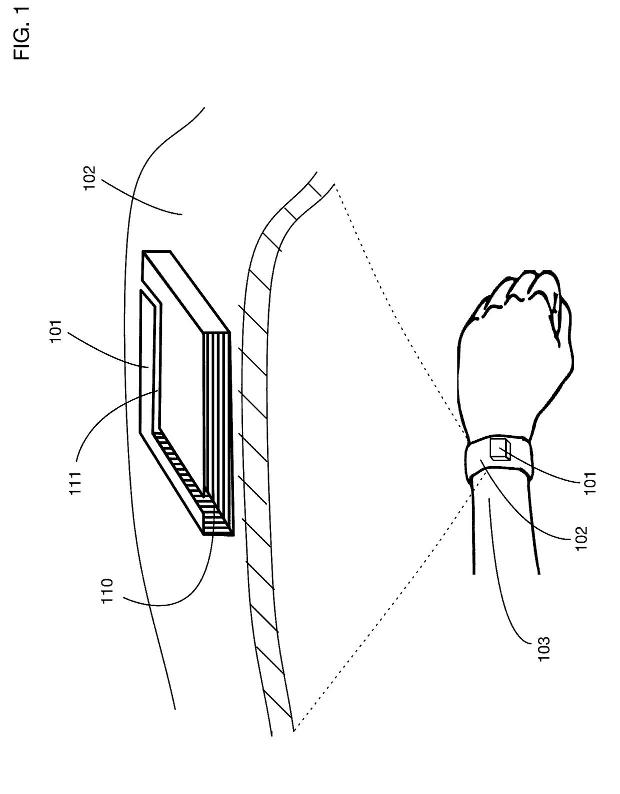
[0060]FIG. 1 illustrates an embodiment of an antenna that may be used with a long-range, surface-insensitive passive RFID tag. This figure shows only the antenna and a mount onto which the antenna is ...


PUM


Abstract

A passive RFID tag that provides long-range reception, even when mounted on a conductive material or a human body. The antenna of the RFID tag is a loop antenna perpendicular to the mounting surface; it may be formed from a tubular sheet of conductive material to reduce conductive losses. An illustrative rectangular loop 1 inch wide by 0.15 inches high by 0.625 inches deep provides a high effective antenna aperture in a compact RFID tag. Multiple mounting positions may be provided for an RFID chip and for a resonating capacitor. Selection of different mounting positions for these components may allow tuning of impedance and resonant frequency without changing components, providing for simpler and more cost-effective manufacturing. The loop antenna may be formed for example from a stamped metal part with a hollow air core, from a double-sided thick PCB, or from an overlay of conductive ink onto a flexible material.

Description

BACKGROUND OF THE INVENTION[0001]Field of the Invention[0002]One or more embodiments of the invention are related to the field of radio-frequency identification (RFID). More particularly, but not by way of limitation, one or more embodiments of the invention enable a passive RFID tag that provides long-range reception and that is insensitive to the surface on which it is mounted.[0003]Description of the Related Art[0004]RFID systems use a specialized interrogator which transmits an RF (radio-frequency) signal and detects the signal reflected by a distant target, known as a “tag”. The passive RFID tag has no battery and no transmitter. The tag has an antenna and a specialized RFID chip. The antenna intercepts a portion of the transmitted energy and delivers it to the chip. In this way, it is similar to the antenna on a conventional radio receiver. The principal difference is that the intercepted RF energy is rectified and used to power the RFID chip. Initially, and prior to powering ...

Claims


Application Information

Patent Timeline
IPC IPC(8): G06K7/08H01Q7/00G06K19/06G06K19/077
CPCG06K19/07773G06K19/07758H01Q7/005H01Q1/2225G06K19/07771
Inventor WEBB, SPENCER
Owner ANTENNASYS
Why Eureka
Try Eureka