Fuel cell module

a fuel cell and module technology, applied in the direction of cell components, electrochemical generators, electrolytes, etc., can solve the problems of insufficient heat energy for heating the oxygen-containing gas supplied to the fuel cell stack, low efficiency, etc., to achieve the effect of reducing waste heat and heat radiation, improving heat efficiency, and facilitating thermal self-sustaining operation

Active Publication Date: 2017-06-06
HONDA MOTOR CO LTD
View PDF18 Cites 4 Cited by
  • Summary
  • Abstract
  • Description
  • Claims
  • Application Information

AI Technical Summary

Benefits of technology

[0010]Further, in the conventional technique 2, long flow channels are adopted to have the sufficient heat transmission area. Therefore, considerably large pressure losses tend to occur. Further, since the heat exchanger 2b containing the cell core 1b is provided, temperature distribution tends to be non-uniform in the fuel cell. Thus, in the case where attempts are made to improve the heat exchange efficiency, great temperature differences occur in the vertical direction or in the lateral direction to cause the heat stress. Accordingly, the durability is degraded.
[0013]The present invention has been made to solve the problems of this type, and an object of the present invention is to provide a fuel cell module having simple and compact structure in which it is possible to achieve improvement in the heat efficiency and facilitate thermally self-sustaining operation, thereby for improving the durability.
[0018]In the structure, generation of the waste heat and heat radiation are suppressed suitably, improvement in the heat efficiency is achieved, and thermally self-sustaining operation can be facilitated. Further, simple and compact structure of the fuel cell module as a whole can be achieved. Thermally self-sustaining operation herein means operation where the operating temperature of the fuel cell is maintained using only heat energy generated in the fuel cell itself, without supplying additional heat from the outside.
[0019]Moreover, the stress relaxing portion for relaxing heat stress is provided at least along the border between the first area and the second area, along the border between the second area and the third area, or along the outermost portion of the third area. In the structure, when the FC peripheral equipment including the exhaust gas combustor, the start-up combustor, the reformer, the heat exchanger, and the evaporator are expanded by heat, the heat stress applied to these components in the radial direction and the axial direction is relaxed by the stress relaxing portion. Accordingly, it becomes possible to suitably suppress degradation in the durability of the FC peripheral equipment due to heat stress.

Problems solved by technology

Therefore, the quantity of heat energy for heating the oxygen-containing gas supplied to the fuel cell stack 1a tends to be insufficient, and the efficiency is low.
Further, temperature distribution tends to be non-uniform in the reaction device 4a due to the heat of the exhaust gas.
Thus, in the case where attempts are made to improve the heat exchange efficiency, great temperature differences occur in the vertical direction or in the lateral direction to cause the heat stress.
Therefore, considerably large pressure losses tend to occur.
Further, since the heat exchanger 2b containing the cell core 1b is provided, temperature distribution tends to be non-uniform in the fuel cell.
Thus, in the case where attempts are made to improve the heat exchange efficiency, great temperature differences occur in the vertical direction or in the lateral direction to cause the heat stress.
Therefore, heat cannot be collected (recovered), and the efficiency is low.

Method used


Image

  • Fuel cell module
  • Fuel cell module
  • Fuel cell module

Examples


first embodiment

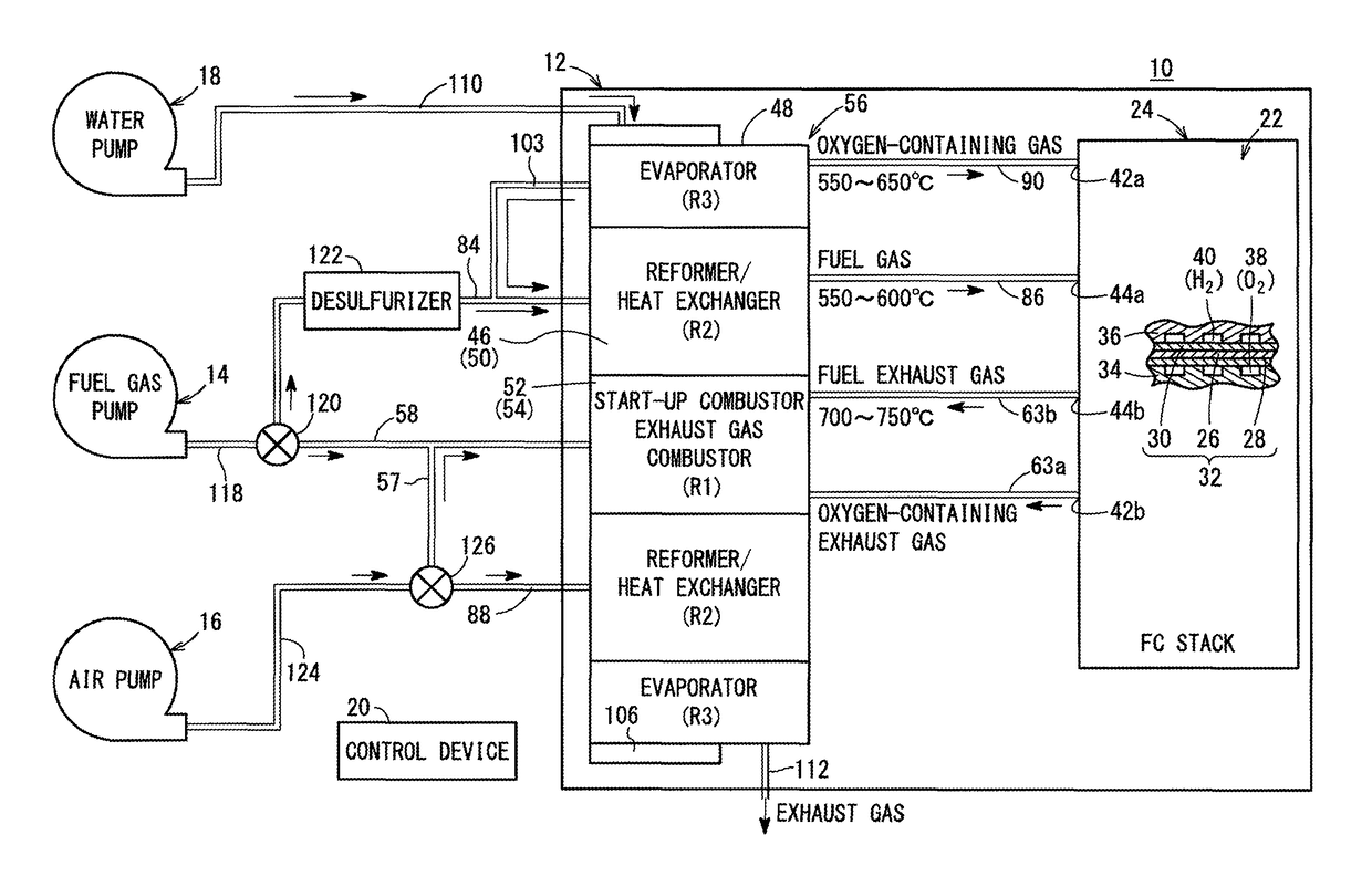
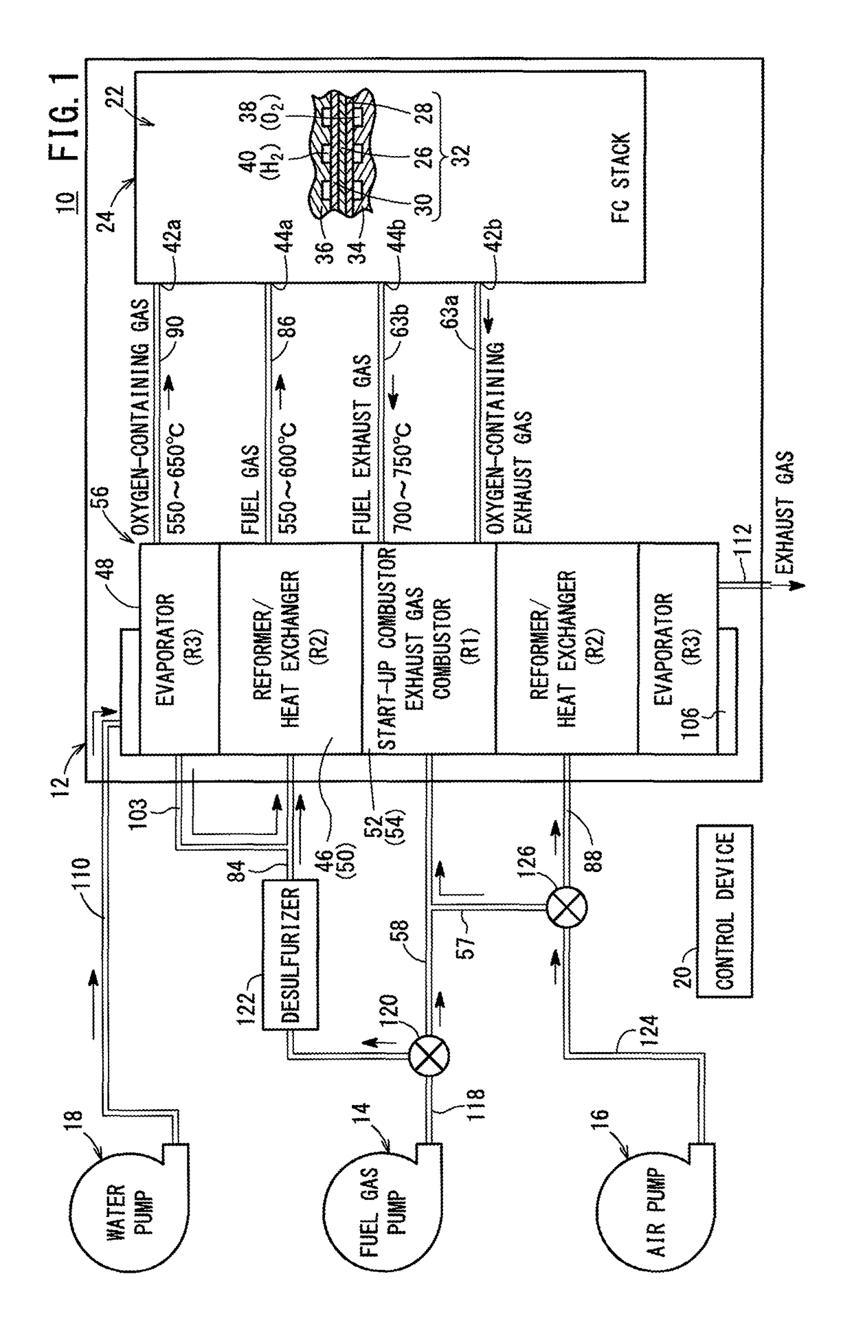
[0036]As shown in FIG. 1, a fuel cell system 10 includes a fuel cell module 12 according to the present invention, and the fuel cell system 10 is used in various applications, including stationary and mobile applications. For example, the fuel cell system 10 is mounted on a vehicle.

[0037]The fuel cell system 10 includes the fuel cell module (SOFC module) 12 for generating electrical energy in power generation by electrochemical reactions of a fuel gas (a gas produced by mixing a hydrogen gas, methane, and carbon monoxide) and an oxygen-containing gas (air), a raw fuel supply apparatus (including a fuel gas pump) 14 for supplying a raw fuel (e.g., city gas) to the fuel cell module 12, an oxygen-containing gas supply apparatus (including an air pump) 16 for supplying the oxygen-containing gas to the fuel cell module 12, a water supply apparatus (including a water pump) 18 for supplying water to the fuel cell module 12, and a control device 20 for controlling the amount of electrical e...

second embodiment

[0114]FIG. 8 is a cross sectional view showing FC peripheral equipment 132 of a fuel cell module 130 according to the present invention.

[0115]The constituent elements of the fuel cell module 130 that are identical to those of the fuel cell module 12 according to the first embodiment are labeled with the same reference numeral, and description thereof will be omitted.

[0116]As shown in FIGS. 8 and 9, in the FC peripheral equipment 132, the reformer 46 is provided outside the heat exchanger 50 in the radial direction in the second area R2. The heat exchanger 50 includes heat exchange pipes 74 arranged along two virtual circles around the first area R1 in a zigzag pattern (in a staggered manner). The reformer 46 includes reforming pipes 66 arranged along a virtual circle around the first area R1, outside the heat exchange pipes 74.

[0117]In the second embodiment, the same advantages as in the case of the first embodiment are obtained.

[0118]In the first and second embodiments, the stress ...


PUM

PropertyMeasurementUnit
operating temperatureaaaaaaaaaa
temperatureaaaaaaaaaa
areaaaaaaaaaaa

Abstract

A fuel cell module includes a first area where an exhaust gas combustor and a start-up combustor are provided, a second area where a reformer and a heat exchanger are provided, and a third area where an evaporator is provided. A stress relaxing portion for relaxing heat stress is provided at least along a border between the first area and the second area, along a border between the second area and the third area, or along an outermost portion of the third area.

Description

TECHNICAL FIELD[0001]The present invention relates to a fuel cell module including a fuel cell stack formed by stacking a plurality of fuel cells for generating electricity by electrochemical reactions of a fuel gas and an oxygen-containing gas.BACKGROUND ART[0002]Typically, a solid oxide fuel cell (SOFC) employs a solid electrolyte of ion-conductive solid oxide such as stabilized zirconia. An anode is provided on one side of the solid electrolyte, and a cathode is provided on the other side of the solid electrolyte to form an electrolyte electrode assembly (MEA). The electrolyte electrode assembly is sandwiched between separators (bipolar plates) to form a fuel cell. In use, generally, predetermined numbers of the electrolyte electrode assemblies and the separators are stacked together to form a fuel cell stack.[0003]As a system including this fuel cell stack, for example, a fuel cell battery disclosed in Japanese Laid-Open Patent Publication No. 2001-236980 (hereinafter referred t...

Claims


Application Information

Patent Timeline
Patent Type & Authority Patents(United States)
IPC IPC(8): H01M8/06H01M8/04119H01M8/04014H01M8/0612H01M8/04223H01M8/243C01B3/38H01M8/124
CPCH01M8/0618C01B3/38H01M8/04022H01M8/04126H01M8/04223H01M8/0631H01M8/243C01B2203/066C01B2203/067C01B2203/1247H01M8/04268H01M2008/1293H01M2300/0074Y02E60/566H01M8/04225Y02E60/50
Inventor YOSHIMINE, YUKIOGAWA, TETSUYA
Owner HONDA MOTOR CO LTD
Why Eureka
Try Eureka