Magnetoresistive magnetic field gradient sensor

a magnetic field gradient and magnetoresistive technology, applied in the direction of magnetic gradient measurement, reference comparison, instruments, etc., can solve the problems of increasing the size and weight of the sensor, reducing the linearity of the sensor, and hall elements generally have high power consumption, so as to achieve wide linear range, high sensitivity, and low power consumption

Active Publication Date: 2017-06-13
MULTIDIMENSION TECH CO LTD
View PDF25 Cites 13 Cited by
  • Summary
  • Abstract
  • Description
  • Claims
  • Application Information

AI Technical Summary

Benefits of technology

[0007]In order to solve these problems, the present invention utilizes MTJ elements as the sensing elements in a magnetoresistive magnetic field gradiometer, which results in the advantages of high sensitivity, wide linear range, low power consumption, small volume, and good temperature performance.
[0016]Adopting the above described features, the present invention will have good external DC magnetic field insensitivity, high gradient sensitivity, wide linear operating range, low power dissipation, small size, and good thermal performance.

Problems solved by technology

Flux concentrators increase the size and weight of the sensor, and can decrease the linearity of the sensor.
Moreover, Hall elements generally have high power consumption.
Although AMR elements have much higher sensitivity than Hall elements, they suffer from narrow linear range, and they need to be reset using a set / reset coil.
The reset operation, resulting increases the complexity of the manufacturing process; the coil increases the size of the sensor; and, the power consumption also increased by the reset operation.
Multilayer GMR sensor elements have higher sensitivity than AMR, but their linear range is low, and unless they are biased by a permanent magnet, the response curve of the can only provide a unipolar measurement of the magnetic field gradient, a bipolar magnetic field gradient cannot be measured.
Although MTJ elements have high sensitivity, when used to detect weak field gradients the MTJ element can be disturbed by strong magnetic fields, and the high sensitivity MTJ elements are not easily amenable to low-cost mass production.
The sensor yield depends on the offset value output from MTJ magnetoresistive element constituting the magnetoresistive bridge, because MTJ elements are often difficult to match on the different arms of the bridge.
The manufacturing process for fully single-chip MTJ sensor bridges is very complicated.

Method used


Image

  • Magnetoresistive magnetic field gradient sensor
  • Magnetoresistive magnetic field gradient sensor
  • Magnetoresistive magnetic field gradient sensor

Examples


Embodiment Construction

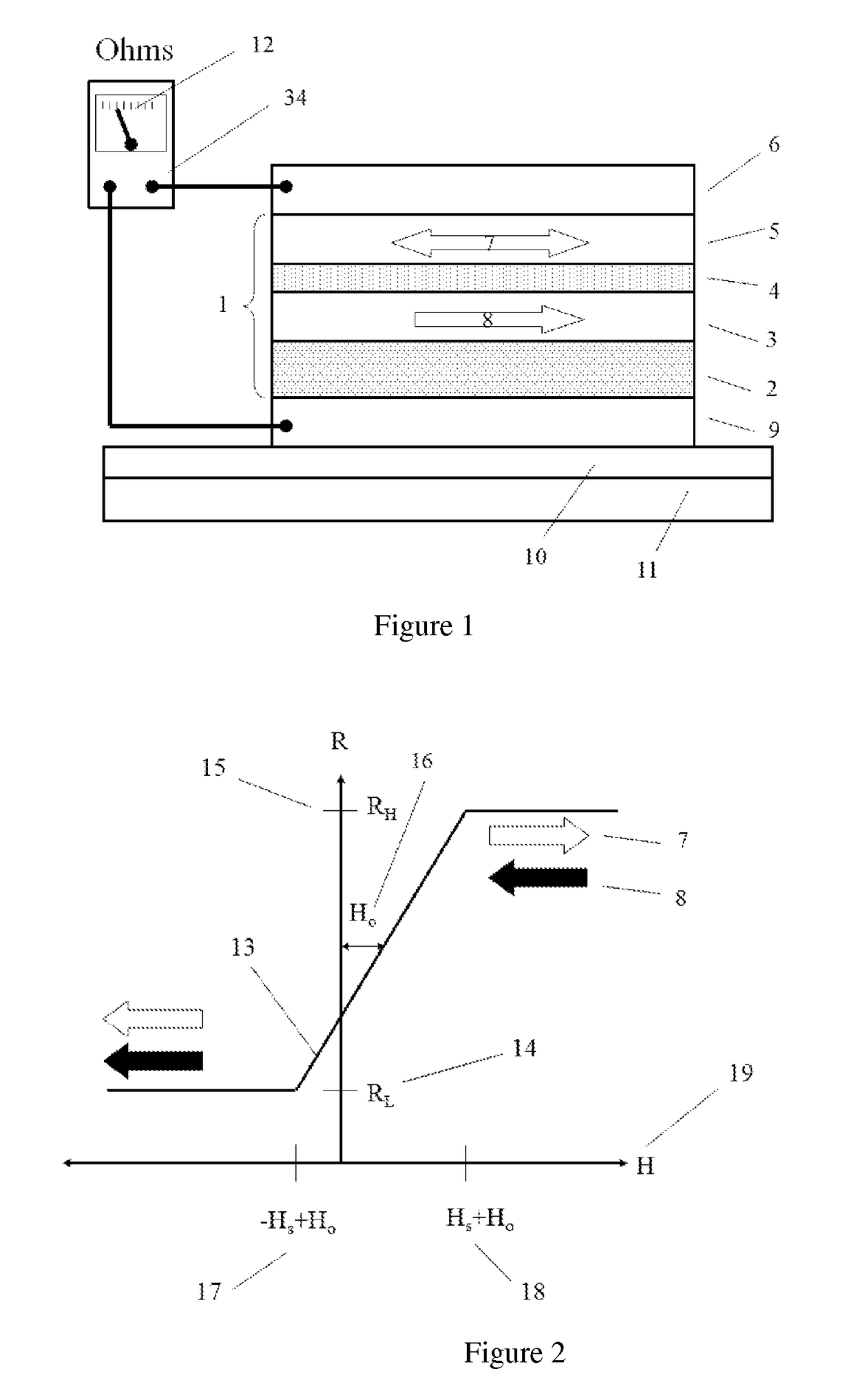
[0028]FIG. 1 is a drawing that illustrates the function of the various layers in an MTJ element. A MTJ element 1 generally includes an upper layer of a ferromagnetic or synthetic antiferromagnetic (SAF) 5, a lower ferromagnetic SAF layer 3, and a tunnel barrier 4 between the two ferromagnetic layers. In this configuration, the upper ferromagnetic (SAF layer) constitutes the magnetic free layer 5, in which the magnetic moment is free to change direction in response to the external magnetic field 7. The lower ferromagnetic (SAF layer) 3 is a fixed magnetic layer, because of its magnetic moment direction 8 is rigidly fixed in one direction, so under normal conditions will not change. Usually the rigidly fixed ferromagnetic layer (SAF layer) 3 is called the pinned layer. The pinned layer is usually adjacent to an antiferromagnetic layer 2. The MTJ stack is usually deposited on top of an electrically conductive bottom electrode layer 9, and the MTJ structure is often capped with a conduc...


PUM


Abstract

Disclosed is a magnetoresistive magnetic field gradient sensor, comprising a substrate, a magnetoresistive bridge and a permanent magnet respectively disposed on the substrate; the magnetoresistive bridge comprises two or more magnetoresistive arms; each magnetoresistive arm consists of one or more magnetoresistive elements; each magnetoresistive element is provided with a magnetic pinning layer; the magnetic pinning layers of all the magnetoresistive elements have the same magnetic moment direction; the permanent magnet is disposed adjacent to each magnetoresistive arm to provide a bias field, and to zero the offset of the response curve of the magnetoresistive element; the magnetoresistive gradiometer includes wire bonding pads that can be electrically interconnected using wire bonding to an ASIC or to the lead frame of a semiconductor chip package.

Description

CROSS-REFERENCE TO A RELATED APPLICATION[0001]This application is a 35 U.S.C. §371 national phase application of PCT / CN2013 / 071090, filed on Jan. 29, 2013, which claims a priority to a Chinese Patent Application No. CN 20120065925.5, filed on Mar. 14, 2012, incorporated herein by reference in its entirety.TECHNICAL FIELD[0002]The present invention relates to magnetoresistive magnetic field gradient sensors, in particular the use of magnetic tunnel junction magnetoresistive sensor elements to form a magnetoresistive magnetic field gradient sensor.BACKGROUND ART[0003]Magnetic field sensors are commonly used in modern systems to measure the magnetic field, current, position, direction, and many other physical parameters. In the prior art, there are many different types of sensors for measuring magnetic field, and these commonly use the Hall Effect, an anisotropic magnetoresistance (AMR), or giant magnetoresistance (GMR) elements.[0004]Hall Effect sensors generally have low sensitivity,...

Claims


Application Information

Patent Timeline
Patent Type & Authority Patents(United States)
IPC IPC(8): G01B7/14G01R17/00G01R33/09G01R33/022
CPCG01R33/098G01R17/00G01R33/022G01R33/09G01R33/093
Inventor BAI, JIANMINDEAK, JAMES GEZALIU, MINGFENGSHEN, WEIFENG
Owner MULTIDIMENSION TECH CO LTD
Why Eureka
Try Eureka