
Wholly optically controlled phased array radar transmitter

a phased array radar and optical control technology, applied in the field of microwave photonics and radar, can solve the problems of limited application in radar imaging, radar working bandwidth, high resolution measurement, etc., and achieve the effect of reducing cost and high efficiency

Active Publication Date: 2017-06-27
SHANGHAI JIAOTONG UNIV
View PDF4 Cites 5 Cited by
  • Summary
  • Abstract
  • Description
  • Claims
  • Application Information

AI Technical Summary

Benefits of technology

This solution provides an ultrabroad bandwidth, eliminates the aperture effect, and allows for compact, cost-effective operation across various microwave frequencies with reduced phase noise, enabling efficient radar signal processing and detection.

Problems solved by technology

However, on one hand, the traditional electronic controlled phased array radar suffers the “aperture effect” of the phased array radar, which limits its application in the fields of radar working bandwidth, high resolution measurement, radar imaging, and spread spectrum code.
On the other hand, restrictions exist for the traditional phased array radar (including optically controlled ones), such as the limited range of tunable microwave signals, limited product of time and bandwidth of radar signals, and strong phase noise.
At certain deviated frequency, bad phase noise characteristics result in that the returned signal is concealed in the phase noise of the carrier wave, and thus, the target may not be properly detected.

Method used


Image

  • Wholly optically controlled phased array radar transmitter
  • Wholly optically controlled phased array radar transmitter
  • Wholly optically controlled phased array radar transmitter

Examples


Embodiment Construction

[0033]In combination with the drawings and an embodiment hereunder provided, the present invention will be further expounded. The embodiment provides detailed implementation means and procedures based on the technical solution of the present invention, and is not meant to limit the scope of the present invention.

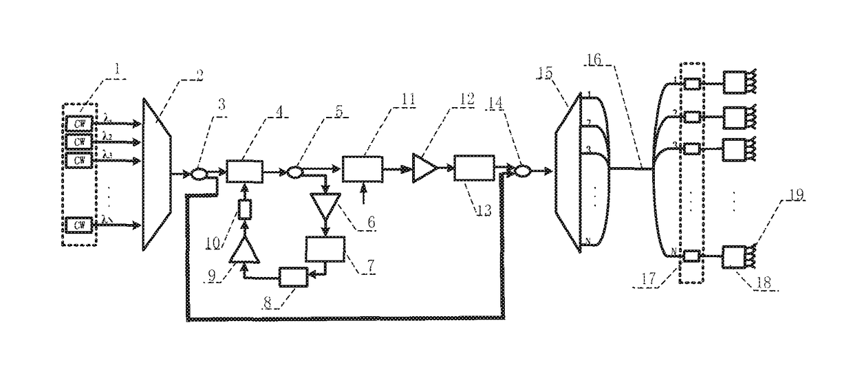
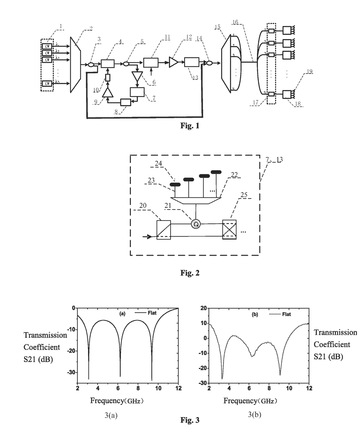
[0034]As shown in FIG. 1, the wholly optically controlled phased array radar transmitter of the present invention comprises a multi-wavelength optical source 1, a first wavelength division multiplexer 2, a first optical splitter 3, a first electro-optic modulator 4, a second optical splitter 5, a first optical amplifier 6, a first optical time delay network 7, a photodetector 8, an electric amplifier 9, a DC-block 10, a second electro-optic modulator 11, a second optical amplifier 12, a second optical time delay network 13, an optical combiner 14, a second wavelength division multiplexer 15, an optical fiber 16, a photodetector array 17, a T / R component array 18, a microwave...


PUM


Abstract

A wholly optically controlled phased array transmitter with integrated tunable optoelectronic oscillators, which are based on multi-wavelength optical sources and optical true time delay units, and optical time delay networks, having a multi-wavelength optical source, a first wavelength division multiplexer, a first optical splitter, a first electro-optic modulator, a second optical splitter, a first optical amplifier, a first optical time delay network, a photodetector, an electric amplifier, a DC-block, a second electro-optic modulator, a second optical amplifier, a second optical time delay network, an optical combiner, a second wavelength division multiplexer, an optical fibers, a photodetector array, a T / R component array, a microwave antenna array, a 1×2 optical switch, a 2×2 optical switch, a circulator, a third wavelength division multiplexer, a bundle of optical fibers with precise lengths, and a Faraday rotation mirror.

Description

CROSS-REFERENCE TO RELATED APPLICATIONS[0001]The subject application is a continuation of PCT international application PCT / CN2014 / 000318 filed on Mar. 24, 2014, which in turn claims priority on Chinese patent applications CN 201410065532.3 filed on Feb. 26, 2014. The contents and subject matter of the PCT and Chinese priority applications are incorporated herein by reference.FIELD OF THE INVENTION[0002]The present invention relates to methods and devices in the fields of microwave photonics and radar, particularly, a wholly optically controlled phased array radar transmitter with integrated optical time delay networks and optoelectronic oscillators based on multi-wavelength optical sources and optical time delay networks.BACKGROUND ART[0003]Phased array antenna system have extensive applications in the fields of radar, communications and electronic countermeasure systems, and the indispensable components include high-quality broad-band tunable microwave signal sources, broad-band r...

Claims


Application Information

Patent Timeline
Patent Type & Authority Patents(United States)
IPC IPC(8): H01Q3/00H01Q3/12H01Q3/26G01S7/282H01Q3/22G01S13/02
CPCG01S7/282H01Q3/2676G01S2013/0245G01S7/4814G01S7/484
Inventor ZOU, WEIWENLIU, CHENJUNYU, ANLIANGCHEN, JIANPING
Owner SHANGHAI JIAOTONG UNIV
Learn More