Vapor cells with transparent alkali source and/or sink

a vapor cell and alkali source technology, applied in the field of alkali and alkaline earth vapor cells, can solve the problems of consuming a large amount of power, difficult to load a precise amount of alkali metal into a miniature vapor cell through the method, and only created applications

Active Publication Date: 2017-09-12
HRL LAB
View PDF1 Cites 12 Cited by
  • Summary
  • Abstract
  • Description
  • Claims
  • Application Information

AI Technical Summary

Benefits of technology

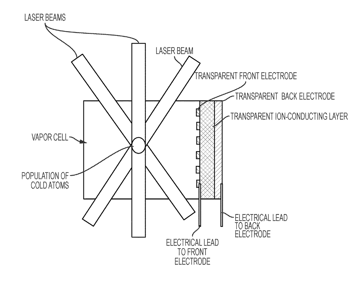
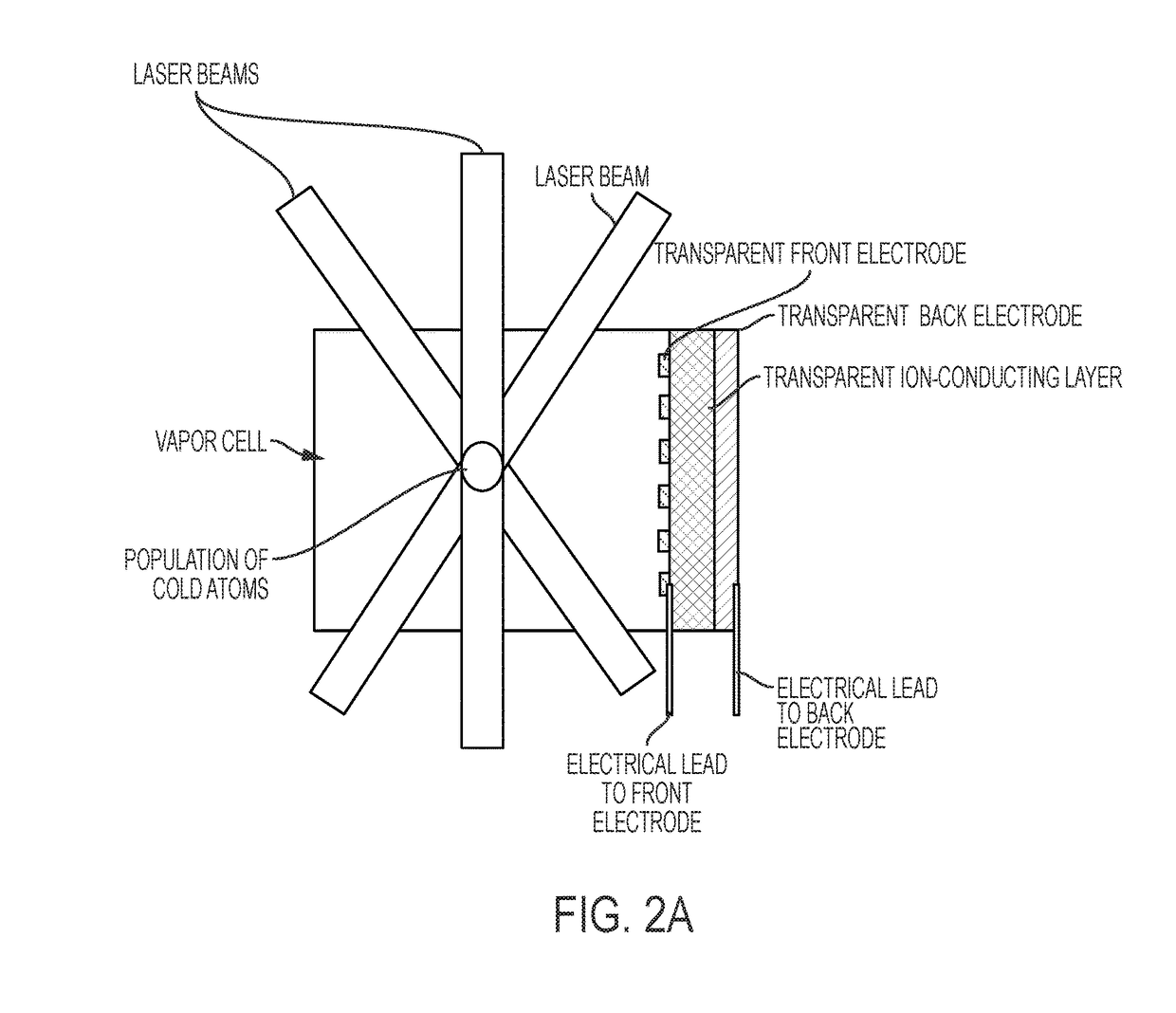
[0065]a source of laser beams configured to provide the three or more vapor-cell optical paths thr

Problems solved by technology

However, most of these applications have only been created in laboratory settings.
Traditional vapor-cell systems are large and, if they have thermal control, have many discrete components and consume a large amount of power.
However, it has proven difficult to load a precise amount of alkali metal into a miniature vapor cell through the methods described in the literature.
Miniature vapor cells have higher surface-area-to-volume ratios than macroscale vapor cells, and are more difficult to load than macroscale vapor cells.
It is difficult to load a precise amount of alkali metal into a miniature vapor cell.
However, these systems are slow, complex, and/or have a short longevity.
Traditionally, alkali metals have been introduced into magneto-optical trap (MOT) vacuum systems via difficult-to-control manual preparation steps, such as manually crushing a sealed alkali-containing glass ampule inside a metal tube connected to the vacuum system via a control valve.
This approach requires external heating to replenish the alkali metal inside the vacuum system as needed (a slow process with little control over the amount of alkali metal delivered).
The manual labor is non-ideal for automated systems or chip-scale devices.
While this process automates the release of alkali metal into the vacuum system, it has difficulty in fabrication compatibility with chip-scale cold-atom devices.
A rapidly pulsed and cooled variant of the alkali metal dispenser has been developed to stabilize

Method used


Image

  • Vapor cells with transparent alkali source and/or sink
  • Vapor cells with transparent alkali source and/or sink
  • Vapor cells with transparent alkali source and/or sink

Examples


Embodiment Construction

[0081]The structures, systems, and methods of the present invention will be described in detail by reference to various non-limiting embodiments.

[0082]This description will enable one skilled in the art to make and use the invention, and it describes several embodiments, adaptations, variations, alternatives, and uses of the invention. These and other embodiments, features, and advantages of the present invention will become more apparent to those skilled in the art when taken with reference to the following detailed description of the invention in conjunction with the accompanying drawings.

[0083]As used in this specification and the appended claims, the singular forms “a,”“an,” and “the” include plural referents unless the context clearly indicates otherwise. Unless defined otherwise, all technical and scientific terms used herein have the same meaning as is commonly understood by one of ordinary skill in the art to which this invention belongs.

[0084]Unless otherwise indicated, all...


PUM


Abstract

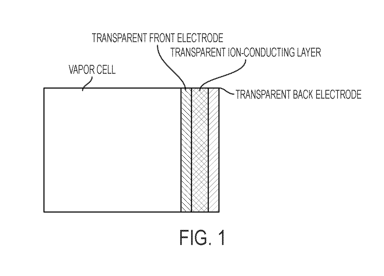
In some variations, a vapor-cell system comprises: a vapor-cell region configured to allow at least one vapor-cell optical path into a vapor phase within the vapor-cell region; a first electrode disposed in contact with the vapor-cell region; a second electrode that is electrically isolated from the first electrode; and a transparent ion-conducting layer interposed between the first electrode and the second electrode, wherein the transparent ion-conducting layer is optically transparent over a selected optical band of electromagnetic wavelengths. Some embodiments provide a magneto-optical trap or atomic-cloud imaging apparatus, comprising: the disclosed vapor-cell system; a source of laser beams configured to provide three orthogonal vapor-cell optical paths through the vapor-cell gas phase, to trap or image a population of cold atoms; and a magnetic-field source configured to generate magnetic fields within the vapor-cell region. Methods of use are also disclosed herein.

Description

PRIORITY DATA[0001]This patent application is a non-provisional application with priority to U.S. Provisional Patent App. No. 62 / 202,525, filed Aug. 7, 2015, which is hereby incorporated by reference herein.STATEMENT REGARDING FEDERALLY SPONSORED RESEARCH OR DEVELOPMENT[0002]This invention was made with Government support under Contract No. N66001-15-C-4027. The Government has certain rights in this invention.FIELD OF THE INVENTION[0003]The present invention generally relates to alkali and alkaline earth vapor cells, systems containing vapor cells, and methods of using vapor cells.BACKGROUND OF THE INVENTION[0004]Alkali vapor-cells have been used extensively since the 1960s in the study of light-atom interactions. Vapor-cell applications, both proposed and realized, include atomic clocks, communication system switches and buffers, single-photon generators and detectors, gas-phase sensors, nonlinear frequency generators, and precision spectroscopy instrumentation. However, most of th...

Claims


Application Information

Patent Timeline
IPC IPC(8): H05H3/02
CPCH05H3/02G04F5/14
Inventor ROPER, CHRISTOPHER S.RAKHER, MATTHEW T.SORENSON, LOGAN D.
Owner HRL LAB
Why Eureka
Try Eureka