Biomedical device, method for manufacturing the same and use thereof

a biomedical device and method technology, applied in the field of implant manufacturing, can solve the problems of incompatible additives, multiple steps, and difficulty in achieving the effect of enhancing linear energy, increasing laser power, and increasing the progression speed of laser beams

Inactive Publication Date: 2018-02-13
NIMAL DIDIER
View PDF17 Cites 0 Cited by
  • Summary
  • Abstract
  • Description
  • Claims
  • Application Information

AI Technical Summary

Benefits of technology

[0035]The term “absorbent” refers to an inorganic additive intended to absorb a proportion of laser energy (i.e. a given range of laser wavelengths) and to dissipate it in another form of energy such as calorific energy. Additive means that the three-dimensional biomedical device substantially does not comprise the absorbent at the end of the manufacturing process, preferably contains less than 0.5% of absorbent. Added to a non-absorbent or poorly absorbent material, the absorbent enhances the laser sintering process by dissipating energy (e.g. calorific energy) to the surrounding material. The absorbent comprises a specific absorptivity higher than the specific absorptivity of the first powder.
[0175]Advantageously, only the first area having the higher porosity is in contact or proximal to the limits or borders of the defects, when in situ, and then promotes cell attachment, proliferation and vascularization. Bioactive material such as ceramic further enhances osseointegration. The second area, with superior mechanical properties, is isolated from tissue by the first area and enhances mechanical properties of the global three-dimensional biomedical device. Each first and second area are sintered deeply enough to bond it together.

Problems solved by technology

Aiming a controlled porosity of these materials while keeping satisfactory mechanical properties, remains the technical challenge of these biomaterials.
This method has the disadvantage of necessitating several steps, first for the manufacture of the substrate and second for the elimination / release of the substrate.
Furthermore, the release of the substrate is susceptible to result in cracking phenomena on the thin walls of the piece.
Most of the time, these additives are not biocompatible.
Moreover, there is a remaining high risk that the step of elimination of the substrate may cause a distortion in the work piece due to variations of the dimensions during the warm-up.
However, this method leads to a filter for filtering fluid such as liquid and gas or the like, and is not adapted for a biomedical device.

Method used


Image

  • Biomedical device, method for manufacturing the same and use thereof
  • Biomedical device, method for manufacturing the same and use thereof
  • Biomedical device, method for manufacturing the same and use thereof

Examples


example 1

[0205]The machine used may be a Phenix® PM100 device commercialized by Phenix Systems®.

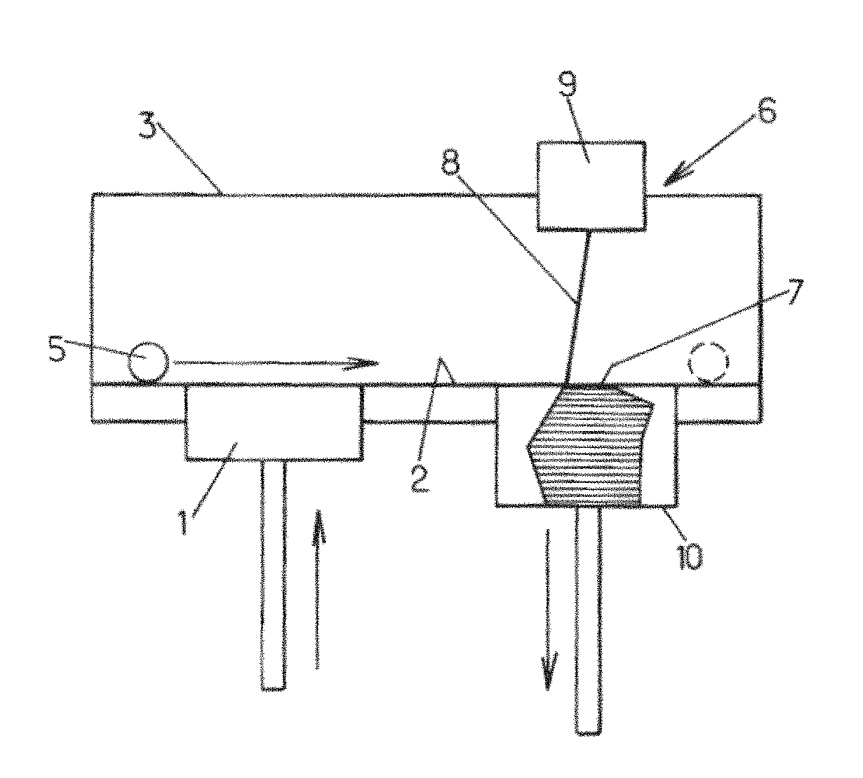
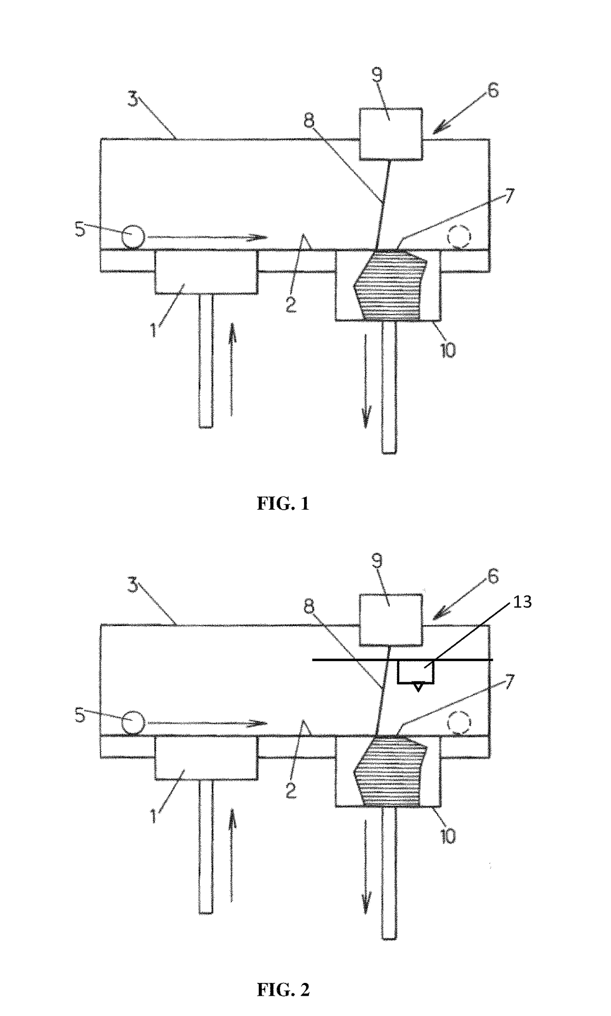
[0206]A ceramic powder of hydroxyapatite having a granulometry 10 to 25 micrometers (commercial reference Medicoat® / Medipure® 20-15, purity>95%) is placed in a container 1 so that it can be layered on a plate 2. The tray 2 may be located in the furnace 3 of the machine 6. The powder may be heated to 800° C. The plate 2 may be supported by a tray 10 movable up and down. The powder is layered with a ceramic roll 5 at a place 7, where it will be processed by a laser beam 8 releases from a galvanometric head 9 (computer directed optical susceptible to direct a laser beam with high speed and high precision). The thickness of the resulting layer is of about 100 micrometers. A laser YAG 160 Watts is preferably used to locally impact and process the powder. The power of the laser beam may preferably be adjusted to 10% of the total power of the laser in order to avoid vitrification of the ceramic powder; t...

example 2

[0213]The example 1 is performed with a mixture of a first powder of hydroxyapatite and an absorbent. A powder of hydroxyapatite, having a granulometry from 5 to 25 nm and a purity above 95% (commercialized by Science Applications Industries) and an absorbent comprising carbon, having a granulometry of 40 nanometers and purity above 97%, are mixed through a wet-process; from 0.1 to 5% by weight of carbon are added to the hydroxyapatite. The mixing is conducted with a laboratory rotary evaporator, called “rotovap”, using methanol as a solvent and alumina balls to promote the mixing. The ratio between the powder and the solvent is (⅓) / (⅔). The settings are the following: temperature of 120° C., speed of 25 rpm (revolution per minute) and duration of 24 hours. The rotary evaporator removes the methanol from the pulverulent substrate by evaporation. By this process, the carbon is well dispersed in the hydroxyapatite powder. The powder is then screened with a mesh size of 50 nm to remove...

example 3

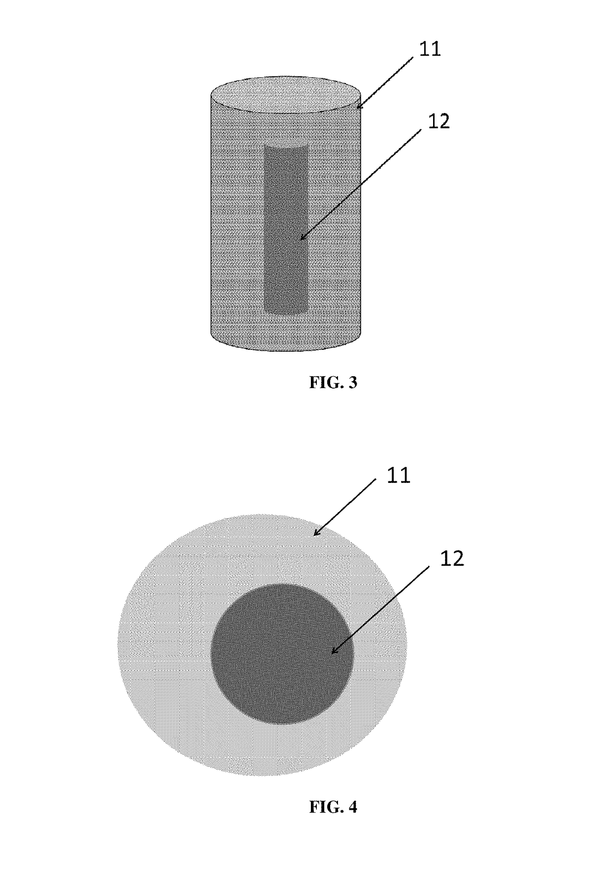
[0215]The example 2 is performed with a progression speed of the laser beam of 100 mm / s. A biomedical device for fitting bone defect having an osteoconductive first area with a controlled porosity and a porous second area is obtained.


PUM

PropertyMeasurementUnit
particle sizeaaaaaaaaaa
thicknessaaaaaaaaaa
temperatureaaaaaaaaaa

Abstract

A method for manufacturing a three-dimensional biomedical device for fitting in a bone defect having an osteoinductive first area with a controlled porosity and a second area, which is produced by laser technology from an absorbent and from a first powder including one of ceramics, metals, metal alloys, bioactive glasses, lead zirconate titanate and biocompatible polymers, or mixtures thereof, wherein the ratio of the porosities from the second area to the first area is equal or less than one, preferably from 0.001 to 0.9, wherein a virtual object is designed with a computer-aid designed software, and the device is manufactured by laser technology including layering a powder onto a plate (7) so that a layer of a predetermined thickness is formed; the laser beam (8) selectively processes the powder to produce a processed layer, and, thus, layer after layer, the layers are joined together until the biomedical device is formed.

Description

[0001]This application is a continuation-in-part of U.S. application Ser. No. 13 / 355,845, filed Jan. 23, 2012, now U.S. Pat. No. 8,862,258.FIELD OF INVENTION[0002]This invention relates to the field of the manufacture of implants for medical and / or orthopedic applications, such as for example prostheses, orthodontia, bone implants, preferably cranial implants. More precisely, the present invention relates to a method of manufacturing a biomedical device from ceramic or metal powder, using a laser technology.BACKGROUND OF INVENTION[0003]The growing search for new materials for orthopedic or reconstruction surgery, leads to the development, in the last two decades, of biomedical devices based on ceramics, such as hydroxyapatite and tricalcium phosphate. These ceramic materials were recognized as biocompatible and as having an osseoconductive behavior, and were thus used for the repair or replacement of bone defects.[0004]Aiming a controlled porosity of these materials while keeping sa...

Claims


Application Information

Patent Timeline
Patent Type & Authority Patents(United States)
IPC IPC(8): B22F3/105B28B1/00B05D1/02C04B35/119A61F2/28B22F3/11A61L27/12A61L27/56C23C16/44B29C67/00B29K101/12
CPCA61F2/28A61L27/12A61L27/56B05D1/02B22F3/1055B22F3/11B28B1/001C04B35/119C23C16/4417B29C64/153Y02P10/295B29K2101/12A61L2430/02B22F2998/10B22F1/02Y02P10/25B22F12/49B22F10/80B22F10/38B22F12/43B22F12/37B22F12/55B22F10/28B22F10/36B22F10/64B22F1/16B22F10/20
Inventor NIMAL, DIDIER
Owner NIMAL DIDIER
Why Eureka
Try Eureka