

Functionalized surfaces and preparation thereof
a technology of functionalized surfaces and surfaces, applied in the field of functionalized surfaces and their preparation, can solve problems such as material incompatibility or contamination
- Summary
- Abstract
- Description
- Claims
- Application Information
AI Technical Summary
Benefits of technology
Problems solved by technology
Method used
Image

Examples
example 1
ial Functionalization of a Surface
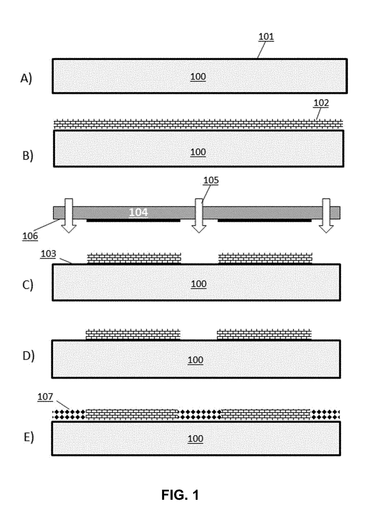
[0164]A structure comprising a 1000 Å layer of silicon dioxide on its top surface was differentially functionalized using a first set of molecules comprising a passive agent (an agent that lacks a reactive group for nucleoside coupling) and a second set of molecules comprising an active agent (an agent that includes an reactive group for nucleoside coupling). The top surface of the structure was coated with the first set of molecules comprising (tridecafluoro-1, 1, 2, 2-tetrahydrooctyl)trichlorosilane using a YES-1224P vapor deposition oven system (Yield Engineering Systems) with the following parameters: 1 torr, 60 min, 70° C. vaporizer. The thickness of the first coated layer was measured using an ellipsometer (J. A. Woollam) to be about 8 Å. The contact angle was measured to be about 115 degrees using a Kruss GmbH instrument.
[0165]The passively coated surface was patterned by application of deep ultraviolet (DUV) light to the top surface of the s...
example 2
eic Acid Synthesis Using a Differentially Functionalized Surface
[0167]The structure having a differentially functionalized surface of Example 1 was used as a support for the synthesis of 50-mer oligonucleic acids. The structure was assembled into a flow cell and connected to an Applied Biosystems ABI394 DNA Synthesizer. Synthesis of the 50-mer oligonucleic acids was performed using the methods of Table 2.
[0168]
TABLE 2General DNA SynthesisStepProcess NameNew Process stepTime#WASH (Acetonitrile WashAcetonitrile System Flush41Flow)Acetonitrile to Flowcell232N2 System Flush43DNA BASE ADDITIONActivator Manifold Flush1.74(Phosphoramidite + ActivatorActivator to Flowcell65Flow)Incubate16Activator +67Phosphoramidite toFlowcellActivator to Flowcell0.58Activator +2.59Phosphoramidite toFlowcellActivator to Flowcell0.510Activator +2.511Phosphoramidite toFlowcellActivator to Flowcell0.512Activator +2.513Phosphoramidite toFlowcellIncubate for 25 sec2514WASH (Acetonitrile WashAcetonitrile System F...
example 3
ial Functionalization of a Surface to Generate a Pattern of Distinct Loci within Clusters
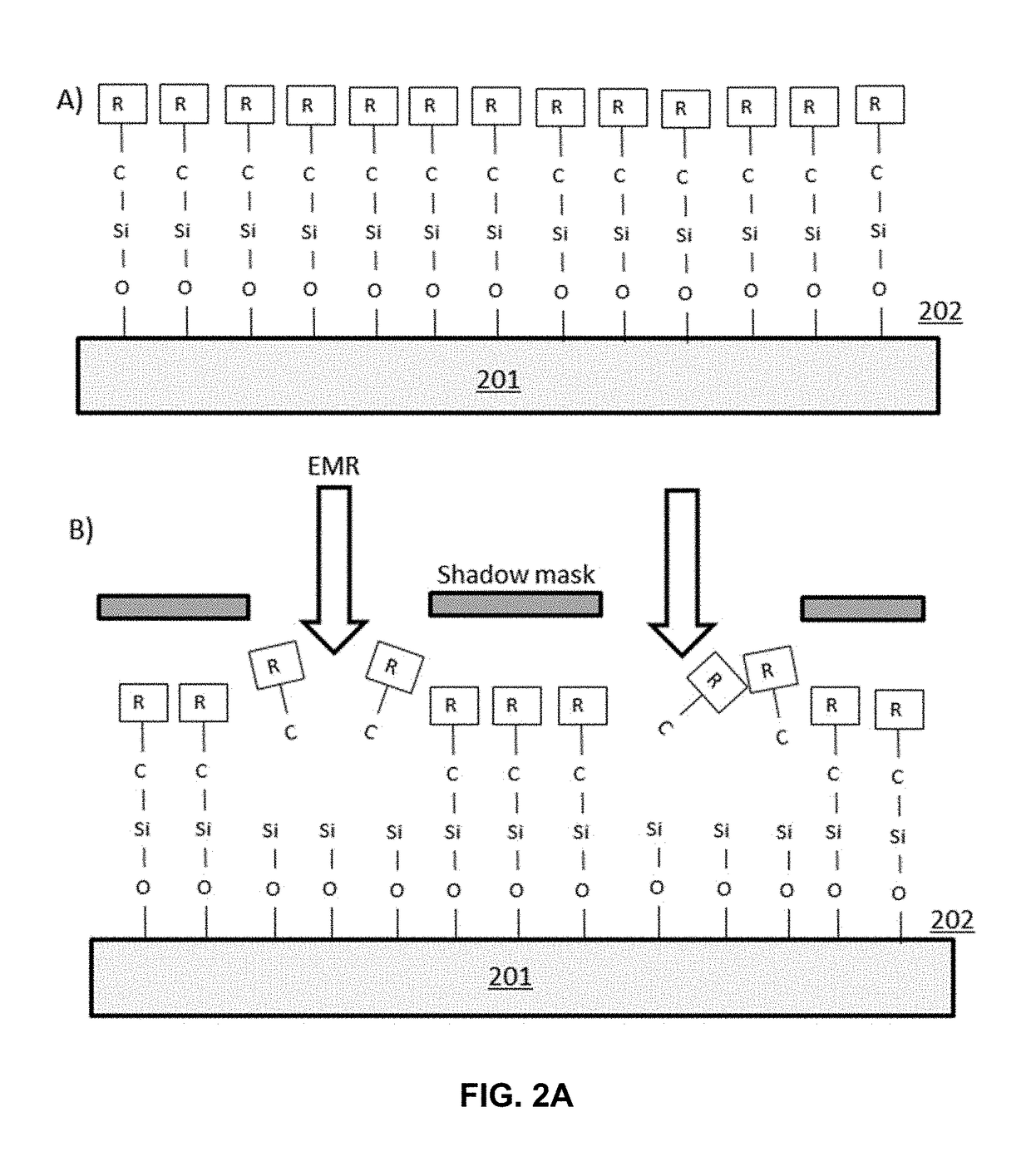
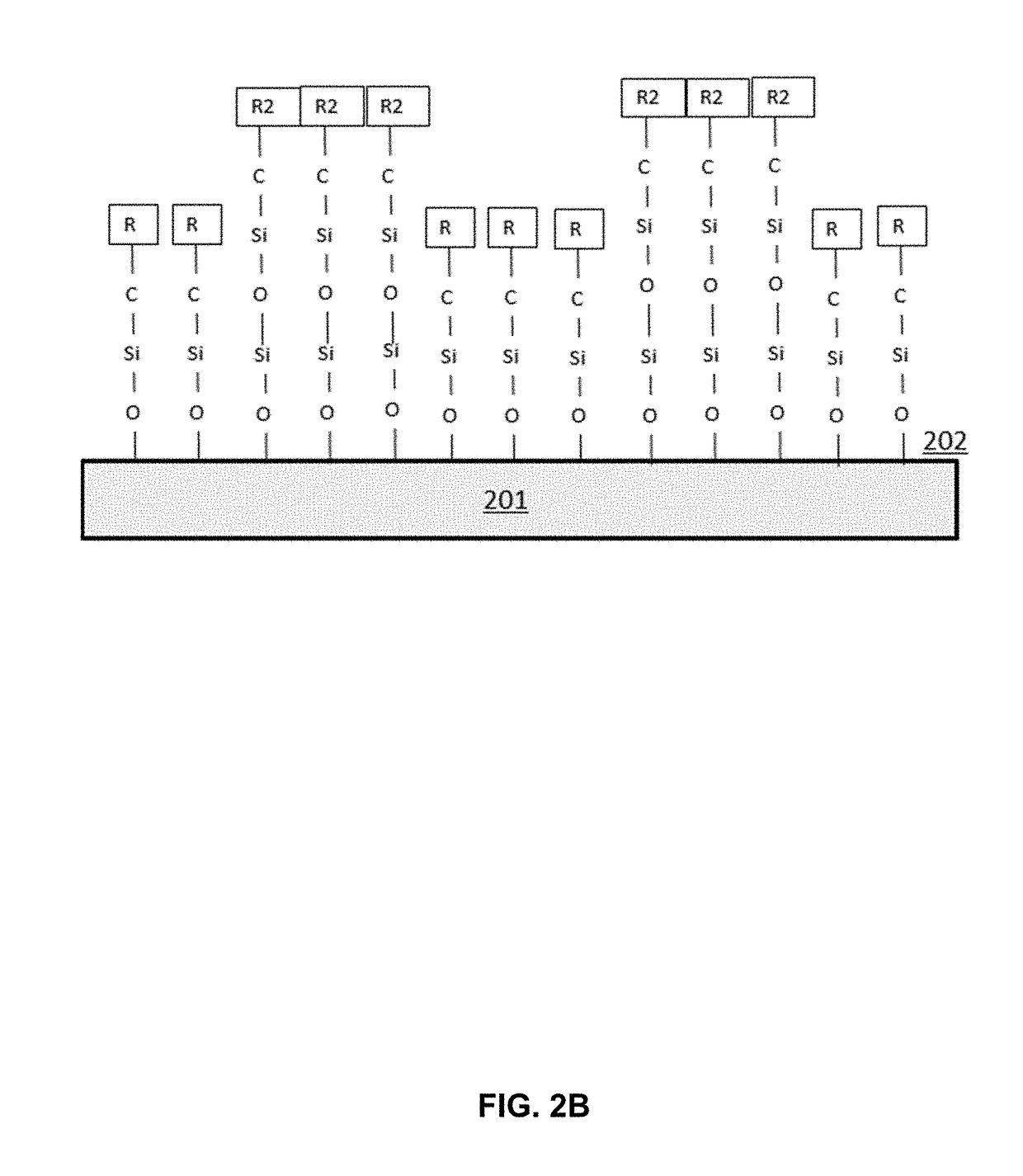
[0170]A structure comprising a 1000 Å layer of silicon dioxide on its top surface was differentially functionalized using a first set of molecules comprising a passive agent (an agent that lacks a reactive group for nucleoside coupling) and a second set of molecules comprising an active agent (an agent that includes an reactive group for nucleoside coupling). The top surface of the silicon surface was coated with the first set of molecules comprising (tridecafluoro-1, 1, 2, 2-tetrahydrooctyl)trichlorosilane as described in Example 1. The passively coated surface was patterned by application of DUV light to the top surface of the structure through a quartz mask with chrome patterns, where the mask was positioned on top of the structure so that only distinct regions of the top surface of the structure were exposed to the DUV light. DUV light was applied using a Hamamatsu L12530 EX-mini Compact Exc...
PUM
| Property | Measurement | Unit |
|---|---|---|
| wavelength | aaaaa | aaaaa |
| width | aaaaa | aaaaa |
| wavelength | aaaaa | aaaaa |
Abstract
Description
Claims
Application Information