Glass/resin composite structure and method for manufacturing same

a composite structure and resin technology, applied in the field of glass/resin composite structure and method for manufacturing same, can solve the problems of inability to produce a high-pressure resistance composite structure that would be suitable, the chemical resistance of the entire composite structure to deteriorate, and the inability to utilize polyether ether ketone resin, etc., to achieve the effect of improving the adhesion between the silica glass and the super enpla, improving the friction between the silica glass and the super

Active Publication Date: 2018-05-22
HITACHI HIGH-TECH CORP
View PDF15 Cites 3 Cited by
  • Summary
  • Abstract
  • Description
  • Claims
  • Application Information

AI Technical Summary

Benefits of technology

[0014]By heating the contact plane between the silica glass substrate and the super enpla substrate to the glass transition temperature or higher of the super enpla, super enpla is softened or liquefied, gaps between the silica glass and the super enpla are eliminated, the silica glass substrate is brought into surface-to-surface contact with the super enpla substrate, and adhesion therebetween is improved as a consequence. In addition, chemical bonding takes place via a hydrolyzable silicon compound between the silica glass and the super enpla at a high temperature of the glass transition temperature or higher, and affinity between the silica glass and the super enpla is improved as a consequence. Further, anchor effects arise as the softened or liquefied super enpla enters into the hydrolyzable silicon compound, and friction between the silica glass and the super enpla is improved. Thus, the composite structure can achieve high-pressure resistance. As the secondary effects, super enpla forms a convex configuration against silica glass on the end plane of the region in which silica glass adheres to super enpla, the effective area of adhesion is increased, and stress concentration is thereby relieved. Thus, pressure resistance is improved. According to the process of the present invention, such effects can be achieved in a single step, and the number of components and the number of steps can be minimized.
[0015]Objectives, constitutions, and effects other than those described above are demonstrated in the embodiments described below.

Problems solved by technology

According to a conventional technique, it was impossible to produce a composite structure with high pressure resistance that would be suitable for a flow channel by reducing the number of components while maintaining the excellent chemical resistance and high chemical resistance inherent in silica glass and super enpla.
This disadvantageously causes the chemical resistance of the entire composite structure to deteriorate, and chemical resistance of silica glass and polyether ether ketone resin cannot be utilized.
According to a method employing pressure bonding, silica glass components are damaged when high degrees of stress are applied.
Thus, high stress cannot be applied, and pressure resistance disadvantageously remains as low as about several MPa.
When super enpla is peeled from the glass as it shrinks at the time of resolidification during the cooling process, gaps are formed at the interface, and liquid leaks through such gaps.

Method used


Image

  • Glass/resin composite structure and method for manufacturing same
  • Glass/resin composite structure and method for manufacturing same
  • Glass/resin composite structure and method for manufacturing same

Examples


Embodiment Construction

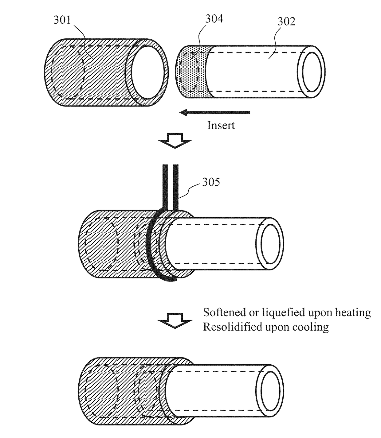
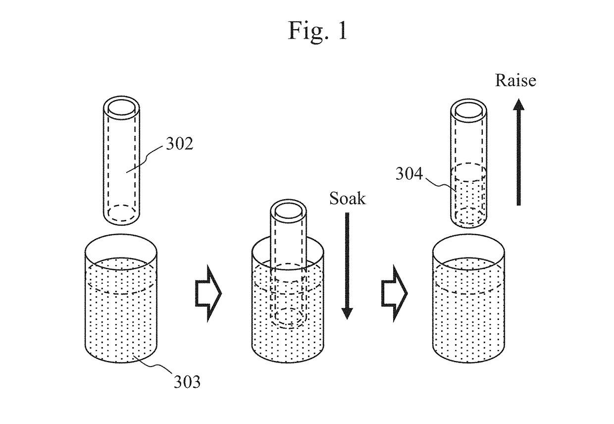
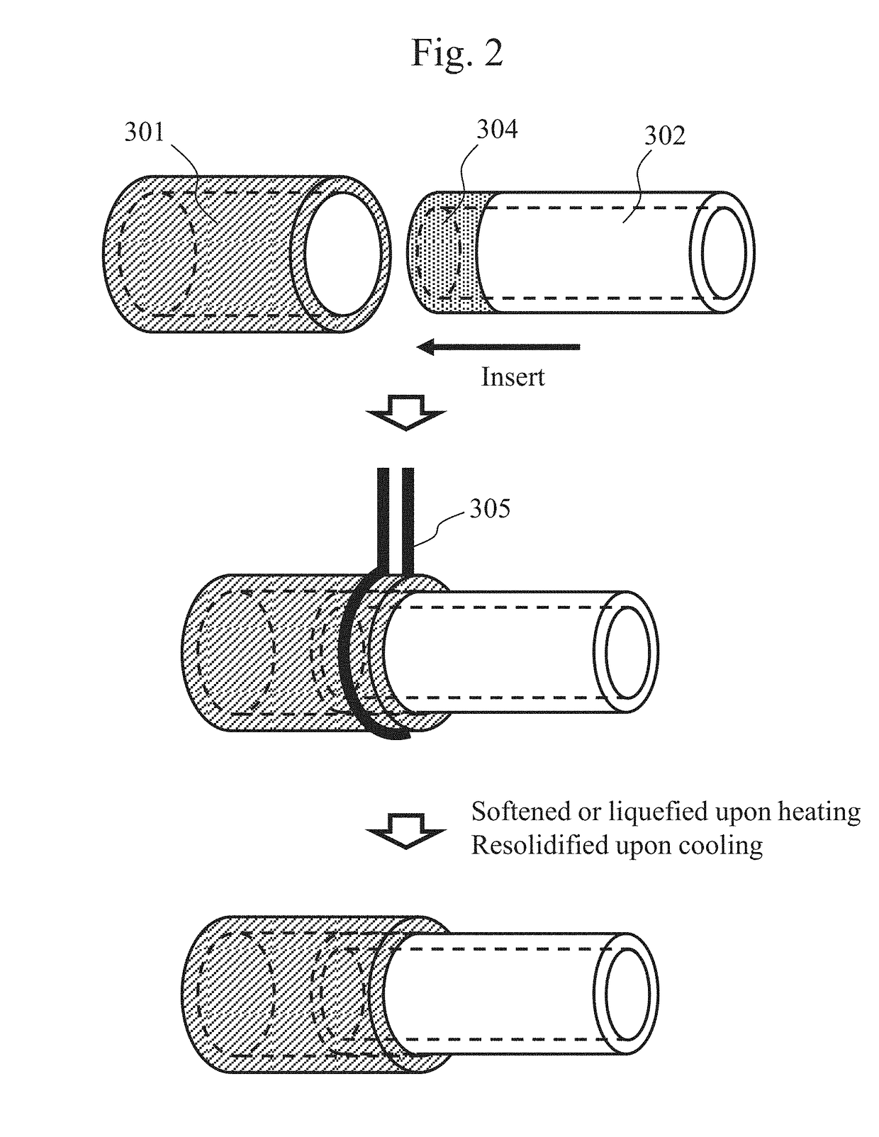
[0043]Hereafter, embodiments of the present invention are described with reference to the drawings.

[0044]In the method of production according to the present invention, a silica glass substrate may be a compound mainly composed of silicon that can chemically bind to a hydrolyzable silicon compound. Preferable examples include synthetic silica glass, fused-silica glass, borosilicate glass, and soda glass having excellent light permeability. According to the present invention, a super enpla substrate is composed of a material having low affinity with silica glass in a softened or liquefied state; that is, a material exhibiting high surface tension between the silica glass and the super enpla. Polyallyl ether ketone-based resins, and, typically, polyether ether ketone resin, polyether ketone resin, polyether ketone ketone resin, polyether nitrile resin, and other resins are preferable. Polysulfone-based resins, such as polysulfone resin, polyphenylene sulfide resin, polyether sulfone r...


PUM

PropertyMeasurementUnit
temperatureaaaaaaaaaa
angleaaaaaaaaaa
temperatureaaaaaaaaaa

Abstract

A composite structure with high pressure resistance that is suitable for a flow channel is produced by reducing the number of components while maintaining the excellent chemical resistance and high stress tolerance inherent to a glass substrate and a resin substrate. A glass substrate surface is modified with a hydrolyzable silicon compound, and the glass substrate is brought into contact with the resin substrate. Subsequently, the contact surface between the glass substrate and the resin substrate is heated to a temperature from the glass transition temperature to the pyrolysis temperature of the resin substrate, eliminating gaps between the glass substrate and the resin substrate to bring them into close contact with each other, and causing chemical binding or anchor effects between the glass substrate and the resin substrate via the hydrolyzable silicon compound. Thus, the glass substrate and the resin substrate are firmly fixed to each other.

Description

TECHNICAL FIELD[0001]The present invention relates to a composite structure of a glass substrate bonded to a resin substrate that is suitable for a flow channel and a method for producing the same.BACKGROUND ART[0002]Use of a wide variety of solvents is required for general-purpose liquid analyzers represented by flow injection analyzers and liquid chromatography apparatuses, and, in general, flow channels in such apparatuses are required to have excellent chemical resistance and high pressure resistance. As materials that satisfy such requirements, organic materials, such as super engineering plastics including polyether ether ketone resin (hereafter abbreviated as “super enpla”), and inorganic materials, such as silica glass and stainless steel, are known. In particular, a combination of silica glass with polyether ether ketone resin is suitable for a material constituting a flow cell for photometric analysis because of properties of silica glass, such as high light permeability i...

Claims


Application Information

Patent Timeline
Patent Type & Authority Patents(United States)
IPC IPC(8): B32B1/08B29C65/46B32B17/06C09J5/06B32B27/28B32B7/12B01L3/00B32B27/36B29C65/48G01N21/05B32B27/34B29K71/00B29L23/00B29L31/00
CPCB32B1/08B29C65/46B29C65/4895B32B7/12B32B17/064B32B27/281B32B27/285B32B27/286B32B27/288B32B27/34B32B27/365C09J5/06G01N21/05B01L3/561Y10T428/1321B01L2300/12B29K2071/00B29K2995/0026B29K2995/0058B29K2995/0077B29L2023/22B29L2031/752B32B2255/20B32B2597/00C09J2400/143C09J2400/226B29C66/73117B29C66/7465B32B17/10B32B17/06
Inventor GOTO, YUSUKEKAMAHORI, MASAOSASAKI, HIROSHIMORI, KIYOTOSHIAKIYAMA, HIDEYUKI
Owner HITACHI HIGH-TECH CORP
Why Eureka
Try Eureka