
Method for linearization of ion currents in a quadrupole mass analyzer

a quadrupole mass analyzer and linearization technology, applied in the field of quadruple mass analyzers, can solve the problems of non-linearity between pressure and ion current, the loss of ions in the high operating pressure area of the quadrupole mass analyzer, etc., and achieve the effect of expanding the pressure range of the gas analyzer

Inactive Publication Date: 2003-06-10
LEYBOLD INFICON
View PDF1 Cites 10 Cited by
  • Summary
  • Abstract
  • Description
  • Claims
  • Application Information

AI Technical Summary

Benefits of technology

An advantage of the present invention is that a linearization factor can be applied to extend the pressure range of a gas analyzer.
is that a linearization factor can be applied to extend the pressure range of a gas analyzer.
Another advantage of the present invention is that each correction factor can be directly applied using software contained in a suitable gas analysis system, or alternately applied using interpolation tables or calculated and applied directly to empirical data.

Problems solved by technology

It has been determined that the transmission of ions in a quadrupole mass spectrometer suffers losses in the high operating pressure area due to several effects; most notably from collisions between ions and neutral gas molecules, ion scattering and coulombic repulsion.
The above effects results in a perceived non-linearity between pressure and ion current.

Method used


Image

  • Method for linearization of ion currents in a quadrupole mass analyzer
  • Method for linearization of ion currents in a quadrupole mass analyzer
  • Method for linearization of ion currents in a quadrupole mass analyzer

Examples


example 1

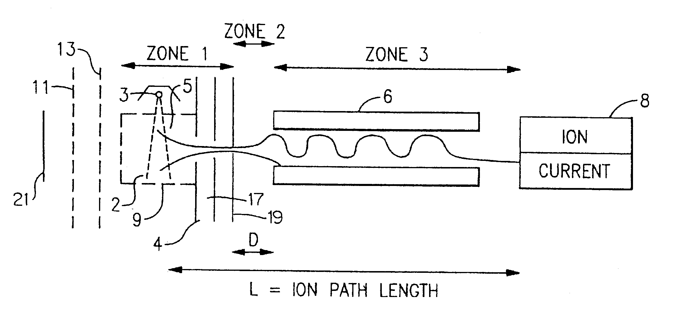
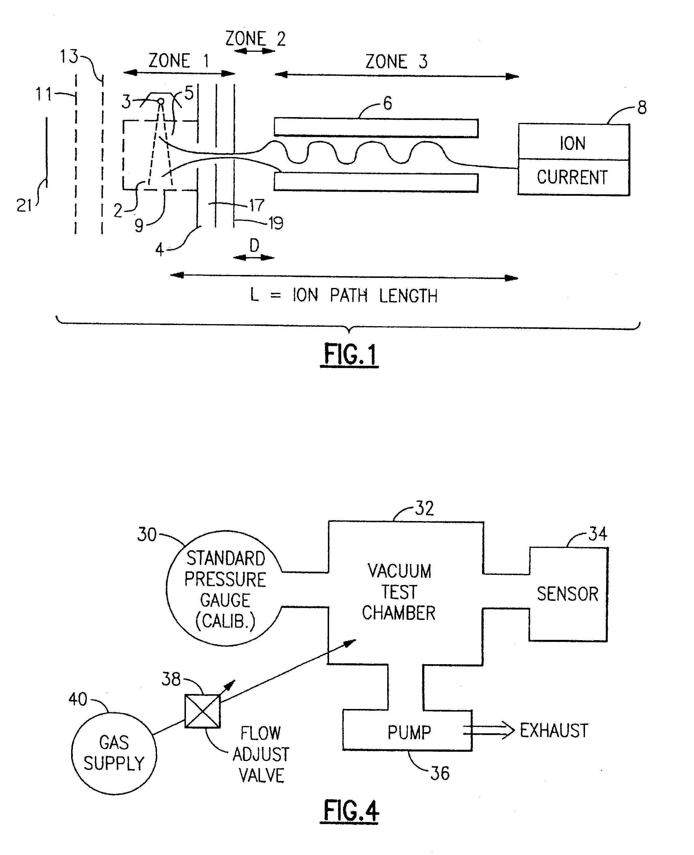
The following example relates to a correction for linearization of ion current for a gas sample of nitrogen using a quadrupole sensing apparatus as illustrated in FIG. 1 or FIG. 4.

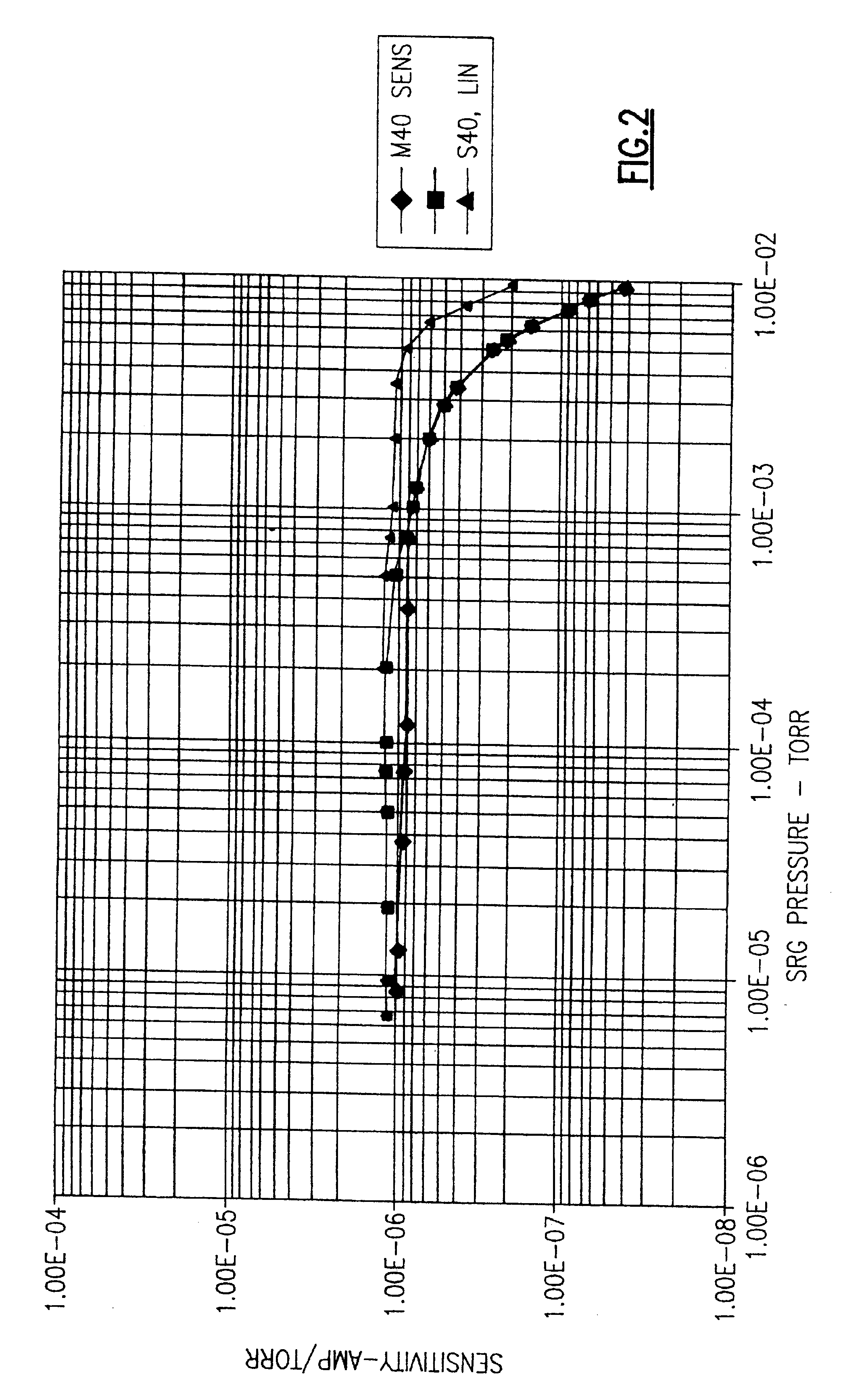
The sensor output signals conducted at 500, 200, and 100 microamp emission currents, were linearized using the above described mathematical relationship. The linearity generated from the tests are shown in FIGS. 5-9.

From FIG. 5, the curve labeled M28, UNLIN represents the normal nitrogen linearity of the sensor system shown in FIG. 1. At 500 microamp emission, the unlinearized mass 28 signal begins to deteriorate from a linear (1:1) relationship at approximately 3.times.10-4 torr, with the signal becoming flat at approximately 4 mtorr.

The total ion source current (labeled ITC) curve is used to calculate the total ion source pressure at each pressure setting. The ion source pressure is determined in the following manner. The sensitivity (S) at each pressure setting is calculated by measuring the partial pre...

example 2

The output signals from a linearity test for a gas mixture were also linearized using the above mathematical relationship, that is using equation (21). The linearity for the test gas mix were conducted at an emission current of 100 microamps. The partial pressures (unlinearized) of the individual gas mix components detected by the gas sensor as plotted against total gas pressure is shown according to FIG. 8. The gas mix used for this specific linearization test is a standard mixture commonly used to tune RGA sensors. The gas mixture consists of the following components:

Hydrogen (M2), Helium (M4), Neon (M20), Nitrogen (M28), Argon (M40), Krypton (M84), and Xenon (not detectable due to setting of the quadrupole mass filter).

Referring to FIG. 8, the curve labeled M#, UNLIN illustrates the unlinearized output of the test mix components detected by the ion detector. The curve (ITC) represents the total ion source current detected at each pressure setting for the gas mix. The total ion cu...


PUM


Abstract

A method for linearizing the sensitivity of a quadrupole mass spectrometric system to allow the sensor to more accurately report partial pressures of a gas in high pressure areas in which the reported data is effected by a number of loss mechanisms. According to the invention, correction factors can be applied empirically or software in a quadrupole mass analyzer system can be equipped with correcting software to expand the useful range of the mass spectrometer.

Description

FIELD OF THE INVENTIONThe invention relates to the field of quadrupole mass analyzers, and more specifically to a method of linearizing ion currents in a quadrupole gas analyzer.BACKGROUND OF THE INVENTIONMass spectrometers include instruments which ionize a gas sample, separate a resulting beam of ions by mass to charge ratio, and then detect filtered ions as an electrical signal. The masses, unique for each substance, identifies the gas molecules from which the ions were created. One such mass filter used is referred to a quadrupole which consists of four parallel electrodes or poles arranged in a square array. Opposite poles are connected together electrically such that an electric field of hyperbolic geometry is produced. Potentials applied to these poles are a superposition of variable DC and RF voltages, generally of a fixed RF frequency.The above instrument works preferably in a high vacuum environment because the ions, once created, must not collide with other gas molecules ...

Claims


Application Information

Patent Timeline
IPC IPC(8): H01J49/34H01J49/02H01J49/42G01N27/62H01J49/26
CPCG01L21/30H01J41/10H01J49/0027H01J49/02H01J49/42
Inventor HOLKEBOER, DAVID H.ELLEFSON, ROBERT E.
Owner LEYBOLD INFICON
Learn More