Cell potential measurement apparatus having a plurality of microelectrodes

a cell potential and microelectrode technology, applied in the field of electric neurophysiology, can solve the problems of damage to cells, difficult multi-point simultaneous measurement, and difficult measurement over a long period of tim

Inactive Publication Date: 2003-11-18
PANASONIC CORP
View PDF26 Cites 59 Cited by
  • Summary
  • Abstract
  • Description
  • Claims
  • Application Information

AI Technical Summary

Benefits of technology

It is preferable that the cell potential measurement apparatus of this invention further comprises an optical observation means for observing the cells optically. It is also preferable that the cell potential measurement apparatus of this invention further comprises a cell culturing means for maintaining an environment for culture of cells which are placed on the integrated cell holding instrument. This configuration enables measurement over a long period of time.
The use of a transparent glass plate as the substrate faciliates optical observations of the cells. Therefore, it is preferable that the conductive patterns or the insulation coating are also substantially transparent or translucent. Furthermore, when the plurality of microelectrodes is arranged in a matrix form, it is easier to specify positions of electrodes which are applied with stimulation signals or electrodes where voltage signals arising from cell activities are detected. For example, it is preferable to arrange 64 microelectrodes in 8 columns and 8 rows. In addition, the surface area of each electrode should be as broad as possible for reducing surface resistance and enhancing detection sensitivity. However, taking restrictions etc. arising from an electrode-to-electrode distance and space resolution of measurement into consideration, it is preferable that each electrode has a surface area of from 4.times.10.sup.2 .mu.m.sup.2 to 4.times.10.sup.4 .mu.m.sup.2.
Furthermore, it is preferable that the electric connection means includes a half-split holder which has a contact touching the electric contact point and fixes the glass plate by holding it from the top and bottom. According to this configuration, fixation of the glass plate and drawing of the microelectrodes to the outside can be performed easily and accurately. Furthermore, it is preferable that the electric connection means not only fixes the holder, but also comprises a printed circuit board having an outside connection pattern which is connected to the contact of the holder via a connector. As a result, connection with outside instruments, namely, with a stimulation signal supply means and a signal processing means is facilitated. For the transmission of stimulation signals or detection signals with as little attenuation and distortion as possible, contact resistance of the electric contact point with the contact as well as contact resistance of the contact with the connector are both preferably below 30 m ohm.
In addition, it is preferable that the optical observation means comprises an optical microscope, and an image pick-up device and an image display device connected to the optical microscope. In other words, the image of cells which is enlarged by a microscope is picked up by an image pick-up device (e.g., video camera) and then displayed in an image display device (e.g., a high-accuracy display), so that it is easier to conduct measurement while observing the cells and the electrode position. More preferably, when the optical observation means is further comprised of an image storage device, it is possible to record measurement results.
It is preferable that a computer is provided to output the stimulation signal via a D / A converter, and at the same time, to receive and process an output signal arising from electric physiological activities of the cells via an A / D converter. As a result, the stimulation signal can be determined as an optional waveform on the screen or a waveform of a detection signal can be displayed on the screen. In addition to these operations, it is easier to display these signals after being processed in various forms or to output them to a plotter or to store them. Furthermore, with the use of this computer, the optical observation means and the cell culturing means can be controlled.

Problems solved by technology

However, measurement by the insertion of these electrodes has the possibility of damaging the cells, and measurement over a long period of time is difficult to carry out.
In addition, due to restrictions of space and the need for operating accuracy, multipoint simultaneous measurements are also difficult to carry out.

Method used


Image

  • Cell potential measurement apparatus having a plurality of microelectrodes
  • Cell potential measurement apparatus having a plurality of microelectrodes
  • Cell potential measurement apparatus having a plurality of microelectrodes

Examples


Embodiment Construction

This invention will now be described in detail by referring to the attached figures and the following examples. The examples are illustrative and should not be construed as limiting the invention in any way.

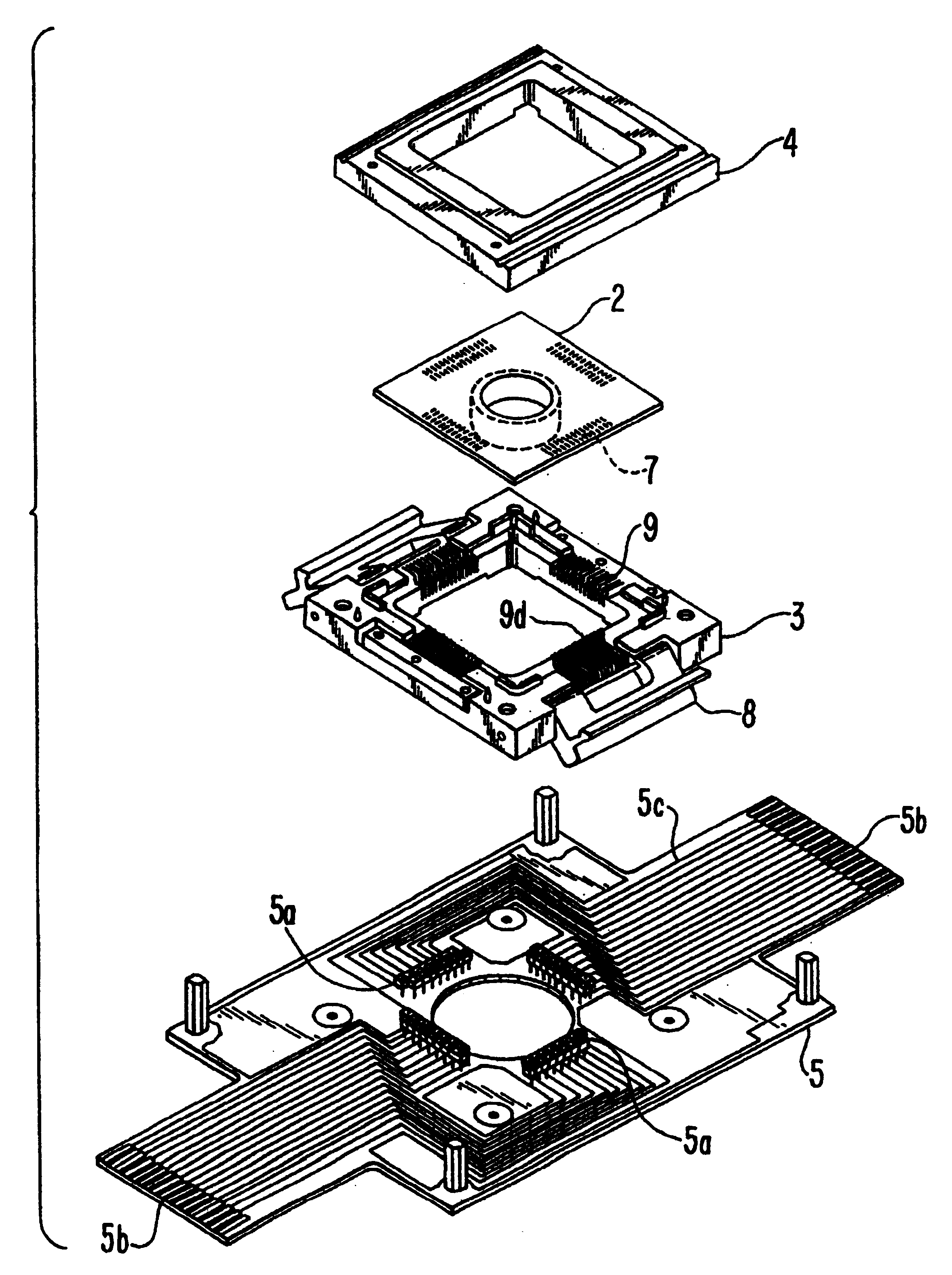
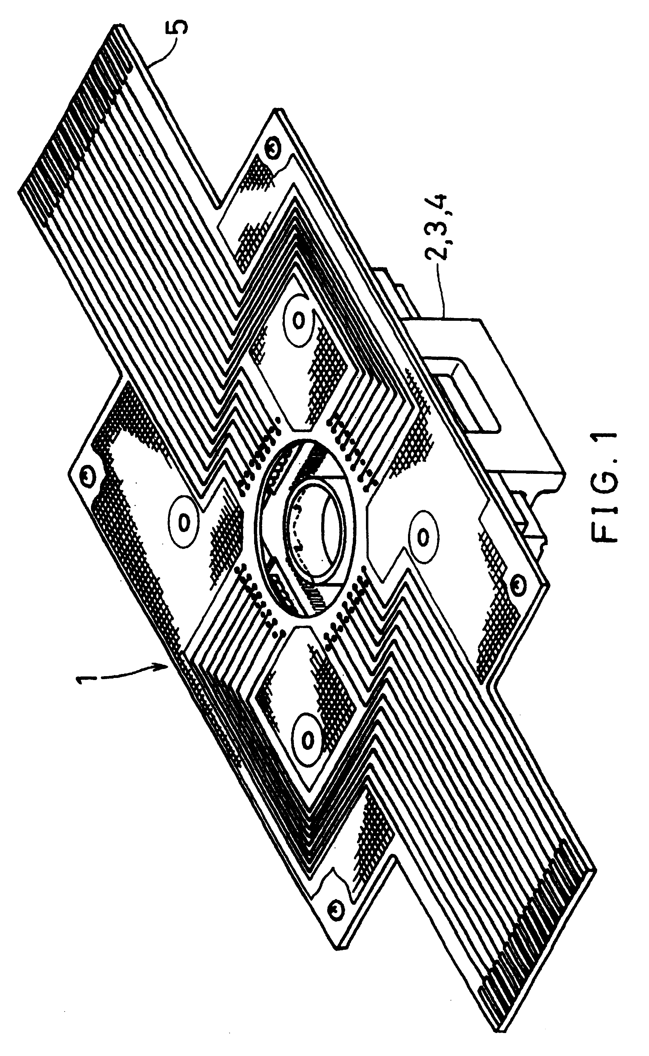
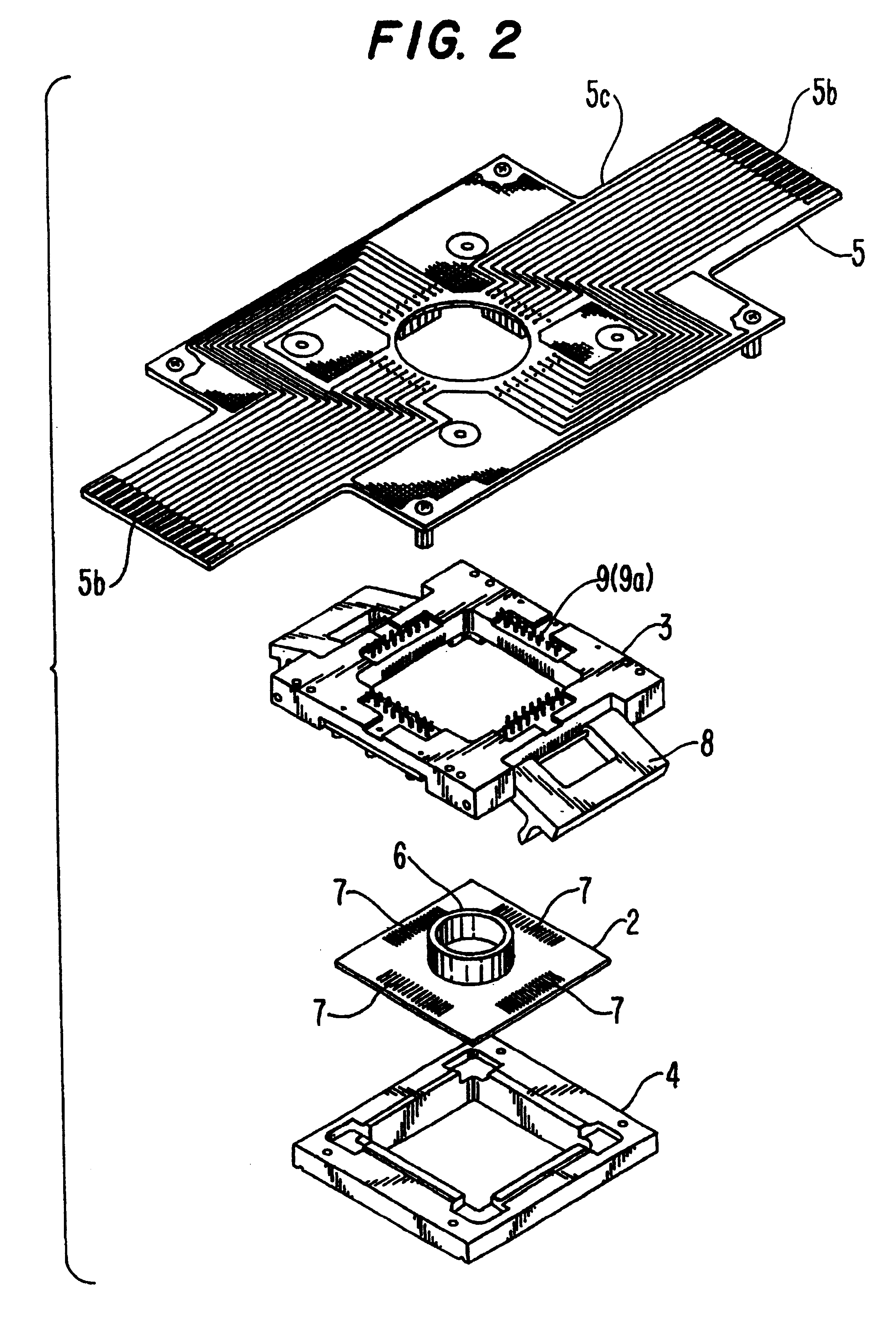
First, an integrated cell holding instrument used for a cell potential measurement apparatus of this invention will be explained. The integrated cell holding instrument 1, as shown as a perspective view in FIG. 1 and as an assembly diagram in FIG. 2, comprises a planar electrode 2, which is disposed with a plurality of microelectrodes and their drawer patterns on the surface of a glass plate, half-split holders 3, 4 for fixing the planar electrode 2 by holding it from the top and bottom, and a printed circuit board 5 on which these holders are fixed.

The planar electrode 2 is approximately the same as that disclosed in Laid-open Japanese patent application No. (Tokkai Hei) 6-78889 and others. The planar electrode 2 comprises, for example, a substrate made of a transparent pilex gl...


PUM

PropertyMeasurementUnit
thicknessaaaaaaaaaa
sizeaaaaaaaaaa
thickaaaaaaaaaa

Abstract

A cell potential measurement apparatus, which uses a planar electrode enabling a multi-point simultaneous measurement of potential change arising from cell activities, is provided which can conduct measurements accurately and efficiently as well as can improve convenience of arranging measurement results. According to the configuration of the cell potential measurement apparatus of this invention, it includes an integrated cell holding instrument 1, which includes a planar electrode provided with a plurality of microelectrodes arranged in a matrix form on the surface of a substrate, a cell holding part for placing cells thereon, drawer patterns from the microelectrodes, and electric contact points for outside connections; an optical observation means 20 for optical observations of cells; a stimulation signal supply means 30 to be connected to the cell holding instrument for providing electric stimulation to the cells; and a signal processing means 30 to be connected to the cell holding instrument for processing an output signal arising from electric physiological activities of the cells. It is preferable that a cell culturing means 40 is also provided for maintaining a culture atmosphere of the cells placed on the integrated cell holding instrument.

Description

FIELD OF THE INVENTIONThis invention relates to a cell potential measurement apparatus which is used in the field of electrical neurophysiology for measuring potential change associated with activities of nerve cells or nerve organs.BACKGROUND OF THE INVENTIONRecently, medical investigations into nerve cells and the possibility of using nerve cells as electric elements have been actively pursued. When nerve cells are active, action potential is generated. This action potential rises from a change in ion concentration inside and outside the cell membrane which is accompanied by a change in ion permeability in nerve cells and thus from the change in cell membrane potential accompanied thereby. Therefore, measuring this potential change accompanied by the ion concentration change (that is, the ion current) near the nerve cells with electrodes enables the detection of activities of nerve cells or nerve organs.In order to measure the above-mentioned potential arising from cell activities...

Claims


Application Information

Patent Timeline
Patent Type & Authority Patents(United States)
IPC IPC(8): C12M1/34G01N33/487G01N27/403
CPCC12M41/46G01N33/4836
Inventor SUGIHARA, HIROKAZUKAMEI, AKIHITOKOBAYASHI, YASUSHITAKETANI, MAKOTOMITSUMATA, TADAYASU
Owner PANASONIC CORP
Why Eureka
Try Eureka