3D AIME™ aircraft navigation

a technology of aircraft navigation and 3d aime, applied in the direction of navigation instruments, using reradiation, instruments, etc., can solve the problems of 50 meters altitude error and less than 20 meters altitude error, and achieve the effect of accurate horizontal position and high integrity

Inactive Publication Date: 2011-11-01
NORTHROP GRUMMAN SYST CORP
View PDF10 Cites 1 Cited by
  • Summary
  • Abstract
  • Description
  • Claims
  • Application Information

AI Technical Summary

Benefits of technology

[0007]The AIME™ mechanization provides accurate horizontal position, with high integrity, which is necessary for accessing stored altitude terrain profile tables along the approach path. This stored terrain profile information could be obtained from contour maps, as used to implement advanced ground proximity warning systems, or from airport surveys. These tables are used to correct radar altimeter measurements for local terrain altitude above sea level to obtain measurements hM(t) of altitude above mean sea level.
[0008]This is normally done with the help of a ground based differential GPS (DGPS) station (“Design and Flight Test of a Differential GPS / Inertial Navigation System for Approach / Landing Guidance”, Journal of the ION, Vol. 38, No. 2, 1991). The differential station is normally necessary since accurate horizontal position is required in order to obtain the correct local altitude from the tables. As an example, in mountainous terrain a 200 meter error in horizontal position can easily result in a 50 meter error in altitude.
[0009]In the 3D AIME™ mechanization of the present invention, the requirement for a differential ground station is avoided. Rather than using the measurements hM(t) directly, they are used to estimate corrections to the baro-inertial output from the IRS. This corrected output is then used for the vertical position output. In this way, the measurements hM(t) over the entire approach, which can extend for 5 to 10 miles, are averaged. A 200 meter error in position will result in an altitude error of less than 20 meters, assuming that the average terrain slope in one direction during the approach is less than 10 percent. Approaches where the average slope in one direction over the entire approach exceeds 10 percent would be rare and would be known in advance.

Problems solved by technology

As an example, in mountainous terrain a 200 meter error in horizontal position can easily result in a 50 meter error in altitude.
A 200 meter error in position will result in an altitude error of less than 20 meters, assuming that the average terrain slope in one direction during the approach is less than 10 percent.

Method used


Image

  • 3D AIME™ aircraft navigation
  • 3D AIME™ aircraft navigation
  • 3D AIME™ aircraft navigation

Examples


Embodiment Construction

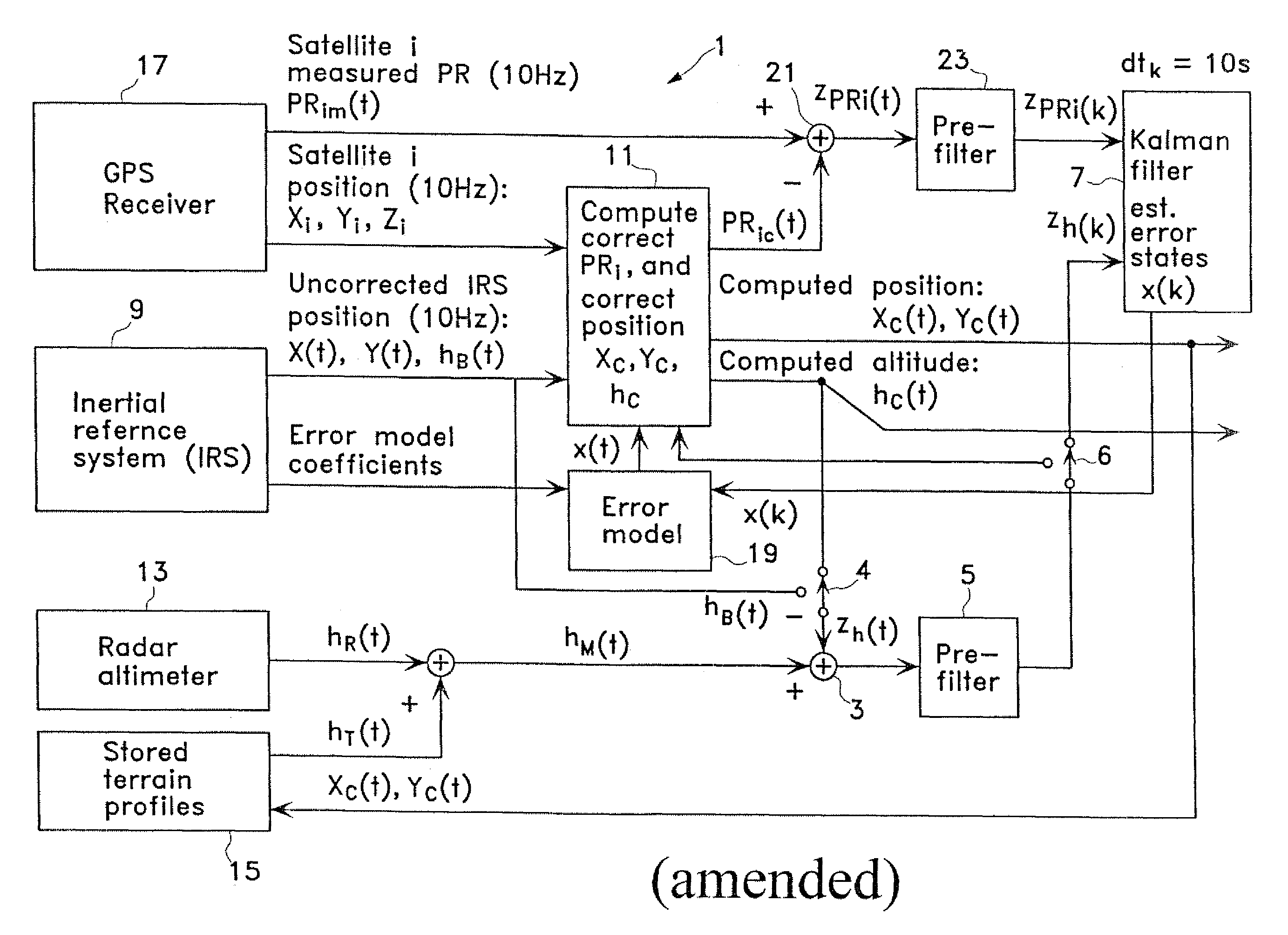
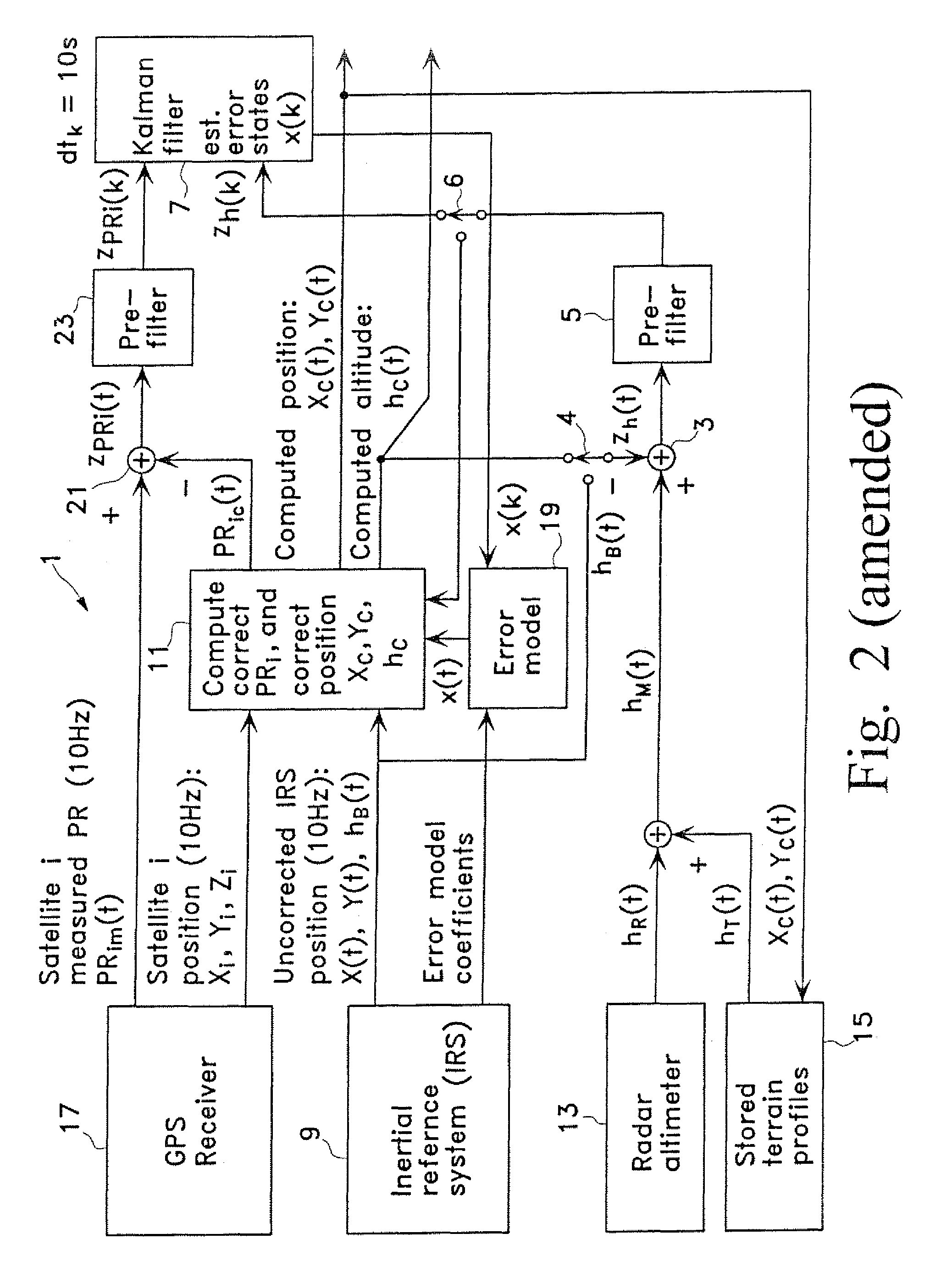
[0013]The apparatus of the present invention is similar in many respects to the apparatus described in U.S. Pat. No. 5,583,774 dated Dec. 10, 1996 (the '774 patent) which is hereby incorporated by reference.

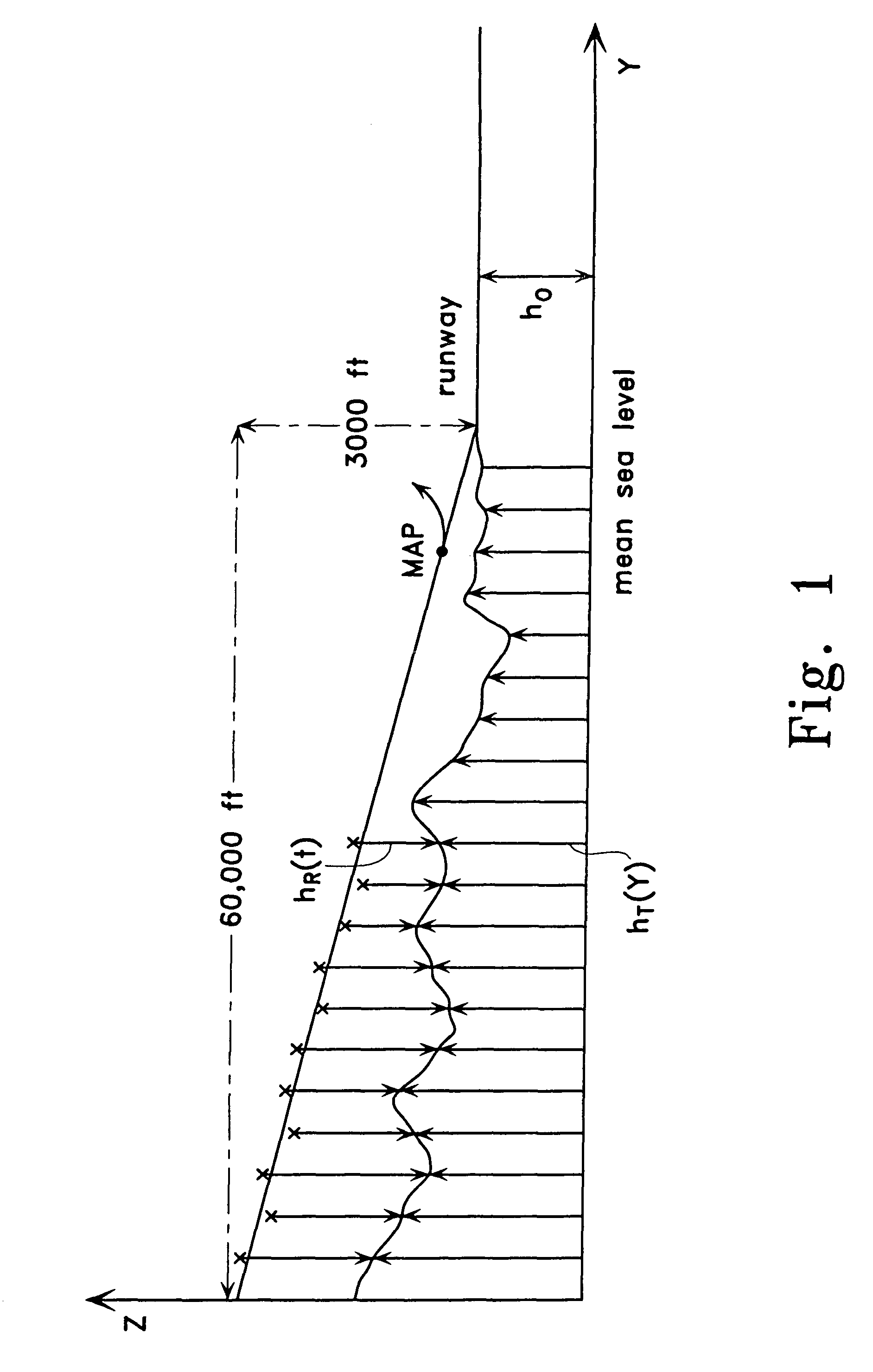
[0014]In the 3D AIME mechanization of the present invention 1 shown in FIG. 2, the measurements hM(t) of altitude above mean sea level (seeFIG. 1) are first referenced to computed altitude hC(t) by adder 3 and then pre-filtered by pre-filter 5. The computed altitude hC(t), as described in the '774 patent, is obtained from computing unit 11 through switch 4. The pre-filtered measurements pass through switch 6 to Kalman filter 7 where they are used as observations in obtaining estimates of the barometric offset at the runway and the barometric scale factor offset from the runway to the aircraft present altitude. The smoothed barometric-inertial altitude from the inertial reference system (IRS) 9 is corrected by these offsets in computing unit 11 to obtain the vertical position outp...


PUM


Abstract

The apparatus of the present invention uses radar altimeter measurements and stored terrain altitude profiles to provide pre-filtered observations to a Kalman filter for estimating barometric offset at the airport runway, and barometric scale factor for offsets above the runway. These offsets are used with the smoothed baro-inertial output from an inertial reference system to provide 3 dimensional constant rate of descent approach procedures to replace non-precision approach procedures based on constant barometric altitude step approaches. The horizontal positions used as reference for the stored terrain altitude profiles are obtained from a prior art navigation apparatus. The integrity of all measurements is assured by using long term averages of the Kalman filter residuals to detect failures. In addition, the estimated baro offset at the runway is compared for consistency with the baro offset obtained by the pilot from the airport by radio.

Description

CROSS-REFERENCE TO RELATED APPLICATIONS[0001]This application claims the benefit of U.S. Provisional Application No. 60 / 067,303, filed Dec. 4, 1997, and U.S. Provisional Application No. 60 / 083,030, filed Apr. 24, 1998.STATEMENT REGARDING FEDERALLY-SPONSORED RESEARCH AND DEVELOPMENT[0002](NOT APPLICABLE)BACKGROUND OF THE INVENTION[0003]Th invention relates generally to aircraft navigation apparatus used during an approach, and more particularly to apparatus combining an inertial reference system (IRS) using air data inputs with the Global Positioning System (GPS) and a radar altimeter. This apparatus can be used on a worldwide basis to replace non-precision approach procedures with 3-dimensional approach procedures, without the use of any ground-based augmentation systems.[0004]It is generally recognized that it will be many years before satellite navigation augmentation systems, such as the wide-area augmentation system (WAAS) and equivalent systems, will provide such a capability....

Claims


Application Information

Patent Timeline
Patent Type & Authority Patents(United States)
IPC IPC(8): G01S13/00G01S13/88G01S5/14G01C21/16B64D45/04G01C5/00G01S13/935G01S19/15G05D1/00
CPCG01S13/882G01S19/15G01S19/49G01C21/1652
Inventor DIESEL, JOHN W.
Owner NORTHROP GRUMMAN SYST CORP
Why Eureka
Try Eureka