

Gas-liquid separator for separating droplet from gas and its separating method
A gas-liquid separation device and separation method technology, applied in separation methods, combined devices, dispersed particle separation, etc., can solve the problems of low gas-liquid separation efficiency, short service life of equipment, etc., achieve simple structure, prolong service life, improve The effect of corrosion resistance
- Summary
- Abstract
- Description
- Claims
- Application Information
AI Technical Summary
Problems solved by technology
Method used
Image

Examples
example 1
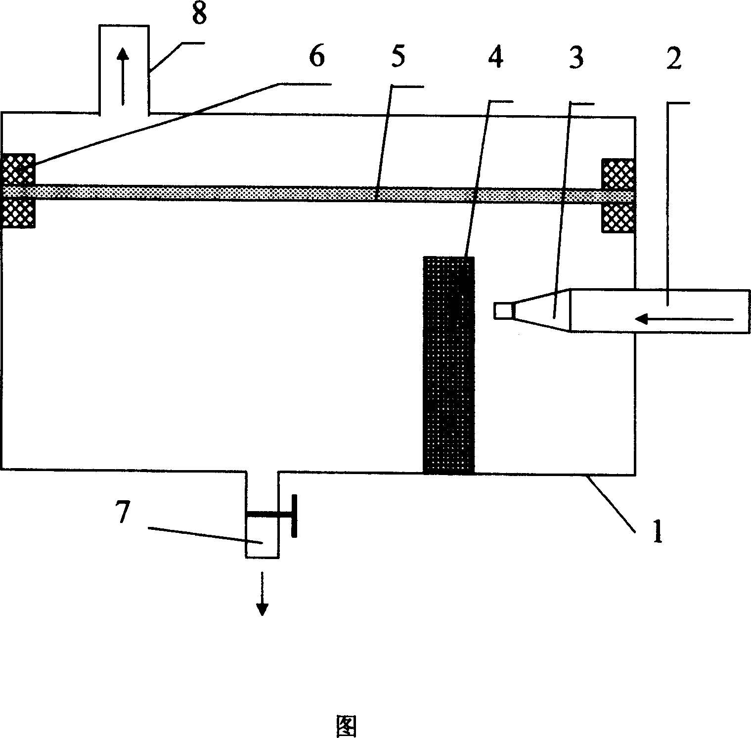
[0026] The gas-liquid separation device of the present invention as shown in the figure is used for the gas-liquid separation of the gas-liquid mixture generated in the gas generating device with a gas flow rate of 2 liters / minute. Wherein, the airtight container (1), the liquid outlet (7) equipped with a one-way valve, the gas outlet (8) and the inlet pipe (2) are made of metal materials; the selected gas jet velocity is 5 m / s, according to the formula The calculated nozzle (3) terminal diameter is 2.9 mm, and the material of the nozzle (3) is a chrome-plated iron alloy; the porous retention felt pad (4) is a porous hydrophilic polytetrafluoroethylene membrane with a thickness of 0.5 mm, and is placed with a support On the inner lower face wall of the sealed container (1) at a distance of 0.5 millimeters from the nozzle (3); above the nozzle (3), the edge tightly pressed sealing body (6) made of silicon rubber is firmly pressed, and the aperture is 0.01 micron, A polypropylen...
example 2
[0029] The gas-liquid separation device of the present invention as shown in the figure is used for the gas-liquid separation of the gas-liquid mixture generated in the gas generating device with a gas flow rate of 1 liter / min. Wherein, the airtight container (1), the liquid outlet (7) equipped with a one-way valve, the gas outlet (8) and the air inlet pipe (2) are made of enamel materials; the selected gas jet velocity is 50 m / s, according to the formula Calculate nozzle (3) diameter to be 0.65 millimeter, the material of nozzle (3) selects the ferroalloy of surface nickel plating; ) 1 mm on the inner lower wall of the sealed container (1); above the nozzle (3) there is an edge-pressed sealing body (6) made of polyurethane rubber that is firmly pressed, the pore diameter is 0.2 microns, and the filtration area is 150 square meters Centimeter polytetrafluoroethylene microporous filter membrane (5).
[0030] Introduce the above-mentioned gas-liquid mixture from the air inlet a...
example 3
[0032] The gas-liquid separation device of the present invention as shown in the figure is used for the gas-liquid separation of the gas-liquid mixture generated in the gas generating device with a gas flow rate of 0.3 liters / min. Wherein, the sealed container (1), the liquid outlet (7) and the gas outlet (8) equipped with a one-way valve are made of enamel materials, and the air inlet pipe (2) is made of metal materials; the selected gas jet flow rate is 100 m / second, the diameter of the nozzle (3) calculated according to the formula is 0.25 mm, and the material of the nozzle (3) is a copper alloy with chrome plating on the surface; the porous retention felt pad (4) is a porous metal sintered body with a thickness of 10 mm, and is placed on the On the inner lower face wall of the sealed container (1) at a distance of 10 mm from the nozzle (3); on the top of the nozzle (3), there is an edge tightly pressed sealing body (6) made of polymer elastic silicone resin, and the apertu...
PUM
| Property | Measurement | Unit |
|---|---|---|
| thickness | aaaaa | aaaaa |
| pore size | aaaaa | aaaaa |
Abstract
Description
Claims
Application Information