Biomass pyrolysis liquefied technique and apparatus system thereof

A technology of biomass pyrolysis and process method, which is applied in the field of biomass regeneration and energy utilization, which can solve the problems of low pyrolysis rate and achieve the effects of shortened gas phase residence time, uniform and stable temperature field, and increased heating rate

Inactive Publication Date: 2008-05-14
CHONGQING UNIV
View PDF8 Cites 2 Cited by
  • Summary
  • Abstract
  • Description
  • Claims
  • Application Information

AI Technical Summary

Problems solved by technology

Therefore, the pyrolysis rate of this application is not high and can only be used for the mechanism research of biomass pyrolysis

Method used


Image

  • Biomass pyrolysis liquefied technique and apparatus system thereof
  • Biomass pyrolysis liquefied technique and apparatus system thereof

Examples


Embodiment 1

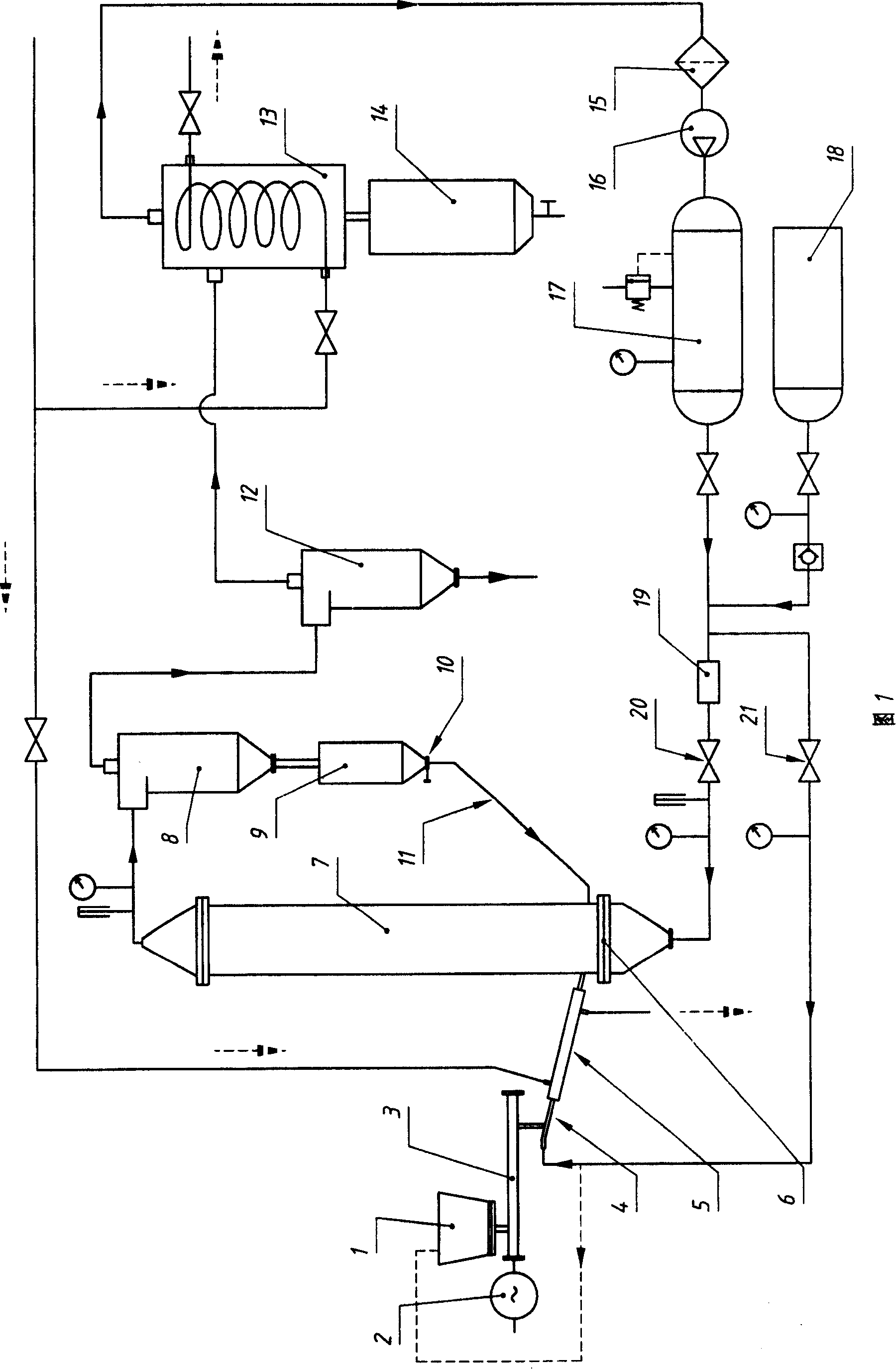
[0036] This example is based on the general description, and is aimed at the further specificity of the way or structure of the heating medium circulation pipe 11 for transporting the heating medium. That is: in the device system of this example, the outlet of the heat carrier heater 9 output heat carrier is higher than the inlet of the pyrolysis reaction tower 7 into the heat carrier, the heat carrier circulation pipe 11 connecting the outlet and the import It is inclined, and the angle between the direction of its inclination and the horizontal plane is greater than 45°. That is to say, in this example, it relies on the gravity of the preheated heating medium itself for transportation. In this way, the operating cost of the system is further saved. Obviously, if each specific device itself and the site allow, the angle between the inclination direction of the heating medium circulation pipe 11 and the horizontal plane can be larger, or the heating medium circulation pipe 11...

Embodiment 2

[0038] This example is based on the general description or Example 1, and is aimed at the further specificity of the way or structure in which carrier gas is used to assist the delivery of biomass powder. That is: in the device system of this example, the feeding mechanism includes a screw conveying device 3 and a feed pipe 4 connecting the outlet of the screw conveying device 3 and the inlet of the pyrolysis reaction tower 7 . The screw conveyor 3 is driven by a variable frequency motor 2 . The carrier gas input pipe connected in the feeding mechanism is connected in the feeding pipe 4 in the structural form of an injector. There is also a branch pipe (drawn with dotted line among the accompanying drawings) at the waist of this carrier gas input pipe, and the outlet of this branch pipe is connected in the charging device 1, and sealing cover is arranged on the feeding port of this charging device 1. That is to say, in this example, the opening adjustment of the heating mediu...

Embodiment 3

[0040] This example is basically the same as Example 2, that is, the feeding mechanism still includes a screw conveying device 3 and a feed pipe 4 connecting the outlet of the screw conveying device 3 and the inlet of the pyrolysis reaction tower 7 . The screw conveyor 3 is driven by a variable frequency motor 2 . The carrier gas input pipe connected in the feeding mechanism is connected in the feeding pipe 4 in the structural form of an injector. The difference is that the dynamic pressure of the carrier gas is greater than the static pressure at the inlet of the pyrolysis reaction tower 7, to allow the carrier gas to carry out auxiliary transportation of the biomass powder in the form of entrainment (because the structural form of the injector belongs to those skilled in the art Clearly, so no partially enlarged cross-sectional view is drawn separately). In other words, when the working condition of the whole system allows the dynamic pressure of the carrier gas to be great...


PUM


Abstract

The invention relates to a biomass analgesic liquidation method and its twin-tower set system, the processes of which comprise the following steps: sending biomass to pyrolytic reaction tower and blending it with high-heat fluidized gas to subject biomass to pyrolytic cracking; separating thermal cracking gas with carbon residue and ash content in separator; and condensing thermal cracking gas to biological oil in condenser. In the process, heat-carrying agent is exported from pyrolytic reaction tower to recycle in the system along with thermal cracking gas, carbon residue and so on. The invention is special for heat-carrying agent separator to separate heat-carrying agent, carbon residue and other materials and thermal fluid heater to heat separated heat-carrying agent. The invention can not only increase circulation rate in system to ensure uniform and stable temperature field in pyrolytic reaction tower, higher heating rates and shorter detention period of gas phase, but also make use of existing apparatus.

Description

technical field [0001] The invention relates to the technical field of biomass regeneration and utilization and its energy conversion, in particular to a process method and a device system for pyrolysis and liquefaction of biomass. Background technique [0002] Energy is the basis for the survival and development of modern society. At present, more than 85% of my country's energy structure is coal, oil, natural gas and other non-renewable fossil fuels. These fossil fuels are not only increasingly scarce, but also cause serious pollution to the environment in the large cycle from mining to utilization. Therefore, seeking renewable clean energy has become a problem of great concern to all countries in the world. Biomass (including various agricultural wastes, fast-growing firewood forests, wastes from forestry and wood processing industries, aquatic plants and various organic wastes, etc.) is the raw material of renewable and clean energy produced through photosynthesis. Bi...

Claims


Application Information

Patent Timeline
Patent Type & Authority Patents(China)
IPC IPC(8): B09B3/00
Inventor 龙恩深周杰陈金华肖益民王亮马校飞
Owner CHONGQING UNIV
Why Eureka
Try Eureka