Micro-thin pen for direct writing electronical photoelectronic component and its constituting device
A technology of optoelectronics and components, applied in the fields of resistors, inductors and optical waveguides, rapid manufacturing of wires, micro pens and devices composed of them, and capacitors, it can solve the problem of small viscosity range of paste, few types of paste, and electronic components. The problem of limited types, etc., achieves the effect of short preparation time, fast wiring speed and low processing cost
- Summary
- Abstract
- Description
- Claims
- Application Information
AI Technical Summary
Problems solved by technology
Method used
Image
Examples
Embodiment 1
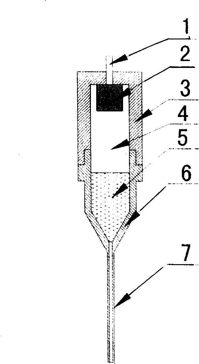
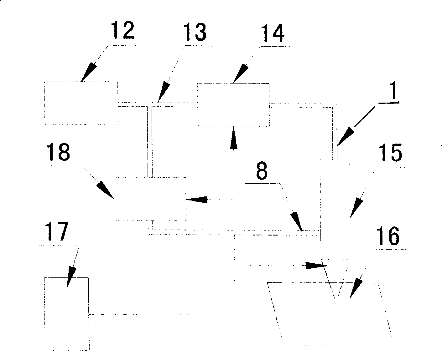
[0026] The composition of the whole fine pen direct writing device is as follows: Figure 4 shown. The first pressure control device 14 and the second pressure control device 18 have the same structure, the former is composed of a pressure regulating valve 25, a pressure gauge 26 and a solenoid valve 27 in series, and the latter is composed of a pressure regulating valve 31, a pressure gauge 30 and a solenoid valve 29 in series made. The compressed nitrogen gas source 19 is connected to the three-way pipe 24 through the gas source switch 20, the pressure gauge 21, the pressure regulating valve 22 and the pressure gauge 23 in sequence. The air pipe is connected with the pressure regulating valve 31. The substrate 16 is located on the workbench 28 , and the controller 17 controls the movement of the workbench 28 through a motor. Micro pen 15 adopts figure 1 In the structure shown, the inner diameter of the nib 7 is 120 μm. When in use, first turn on the gas source switch 20...
Embodiment 2
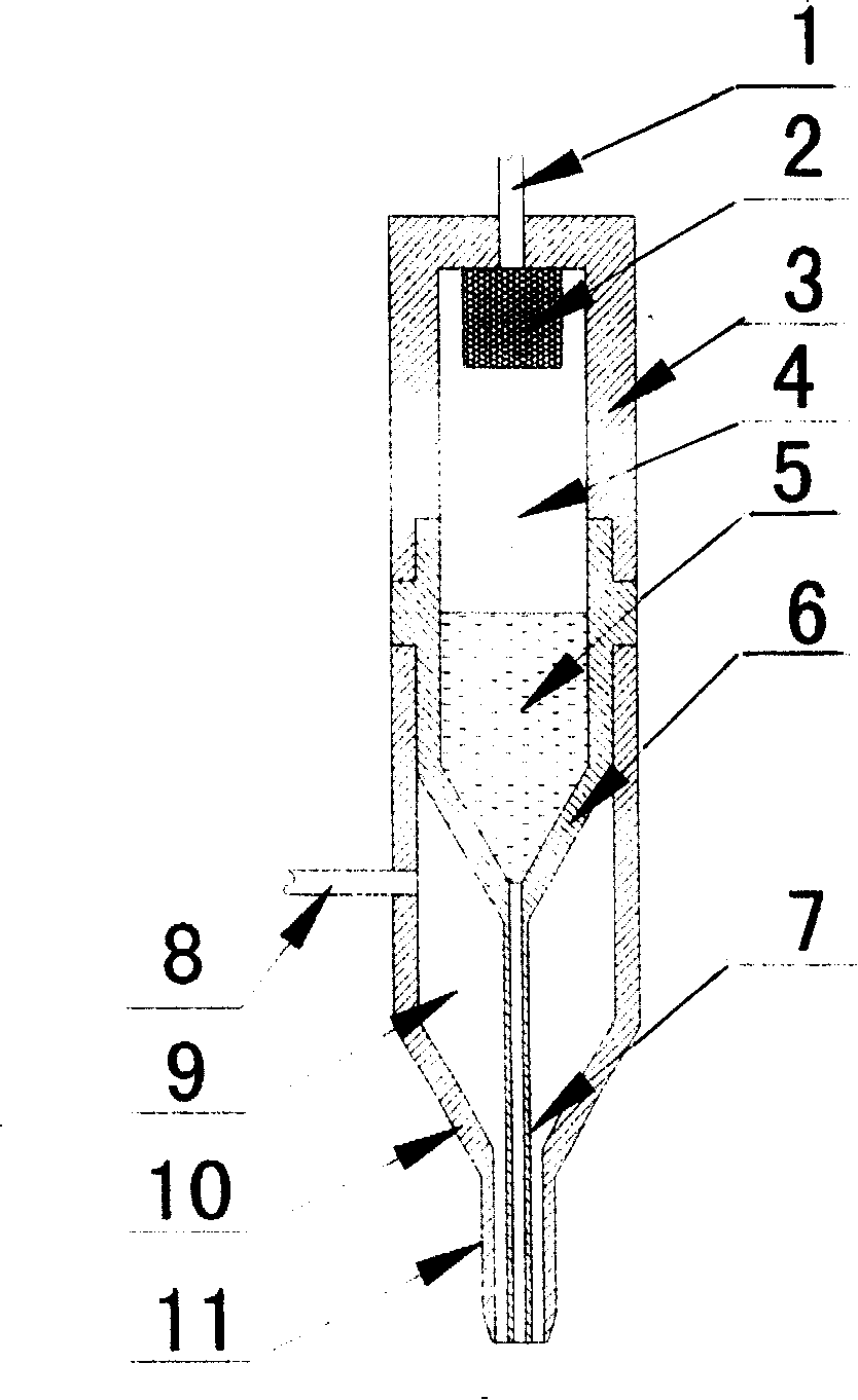
[0030] when according to figure 2 When the fine pen shown in the figure is used for jet direct writing, it needs to be turned on Figure 4 The second pressure control device 18 shown is the atomizing gas circuit. In jet direct writing, the inner diameter of the pen tip 7 is 120 μm, the outer diameter is 180 μm, and the gap between the pen tip 7 and the air nozzle 11 is 10 μm.
[0031] Using such a device structure can realize direct writing based on jetting principle. In direct writing, the slurry will be atomized first, and then deposited on the substrate, and different shapes can be obtained by controlling the movement of the worktable. When atomizing direct writing, the tip of the pen does not touch the substrate, so electronic components can be made on curved surfaces; at the same time, the atomization has a divergent effect on the slurry, and the resolution of the line width will decrease during direct writing, but when it needs to be It has advantages when writing di...
Embodiment 3
[0035] The device used is the same as in Example 1, and the operation mode and steps are the same as in Example 1. However, the electronic paste is replaced by a polymer with excellent performance, and the device can be used to write directly to the optical waveguide.
[0036] Adjust the air pressure and other parameters, set the control program, and after debugging the device, put fluorinated polyimide (PI) in the micropen, start the device, and then write the optical waveguide on the silicon substrate with a waveguide width of about 100 microns , with a thickness of about 5 microns. The prepared optical waveguide is subjected to a light transmission experiment to test the loss of the optical waveguide, and the minimum loss can reach 0.5dB / cm, which can meet the manufacturing requirements of optoelectronic devices.
PUM
 Abstract
Description
Claims
Application Information
 - R&D
- Intellectual Property
- Life Sciences
- Materials
- Tech Scout
- Unparalleled Data Quality
- Higher Quality Content
- 60% Fewer Hallucinations
Browse by: Latest US Patents, China's latest patents, Technical Efficacy Thesaurus, Application Domain, Technology Topic, Popular Technical Reports.
© 2025 PatSnap. All rights reserved.Legal|Privacy policy|Modern Slavery Act Transparency Statement|Sitemap|About US| Contact US: help@patsnap.com


