Gasoline engine

A gasoline engine and fuel oil technology, applied in the direction of engine components, machines/engines, cylinders, etc., can solve the problems of power reduction, difficult exhaust gas emission, waste of energy, etc., to achieve improved power conversion efficiency, reasonable piston movement, and reduced operating costs Effect

Inactive Publication Date: 2008-09-17
李鱼飞
View PDF5 Cites 7 Cited by
  • Summary
  • Abstract
  • Description
  • Claims
  • Application Information

AI Technical Summary

Problems solved by technology

[0002] As we all know, the power of the current engine is transmitted by the rotational torque of the crankshaft, and the force obtained by the crankshaft comes from the piston connecting rod mechanism. When the crank is in a vertical state, the length of the torque arm is zero. Only when the crankshaft rotates 90°, the crankshaft’s moment arm is the longest. Therefore, the conversion efficiency of the force on the piston connecting rod to the crankshaft and then to the crankshaft is less than 0.5 , when the conversion efficiency reaches 1 or close to 1, it is highly efficient, and it is also the direction people are pursuing.
And the current engine is difficult to exhaust the exhaust gas
[0003] In addition, due to the movement mode of the crank connecting rod and piston in the past, the piston generates lateral force during operation, resulting in uneven wear of the cylinder wall, which often presents an elliptical shape, causing oil leakage in the engine, reducing power, and requiring overhaul.
In a word, due to the structural form of the crankshaft and piston connecting rod in the past, the defects of energy waste, low work efficiency, and low conversion efficiency have inevitably occurred. This has attracted the attention of colleagues at home and abroad, and they are all developing high-efficiency automotive engines , but unfortunately so far, no successful reports have been seen

Method used


Image

  • Gasoline engine
  • Gasoline engine
  • Gasoline engine

Examples


Embodiment Construction

[0021] Embodiments of the present invention are described in detail with reference to the accompanying drawings, but are not limited by the embodiments.

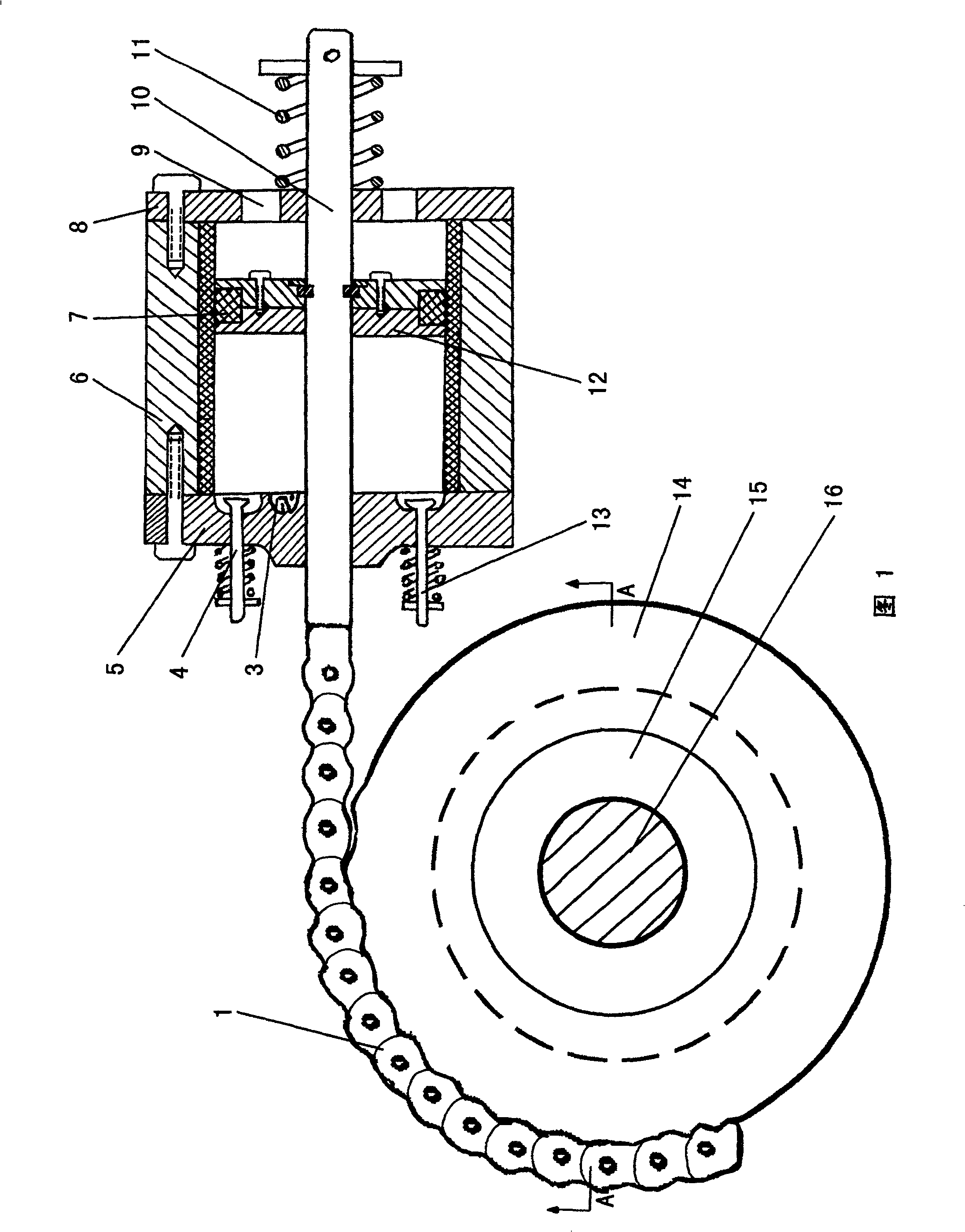
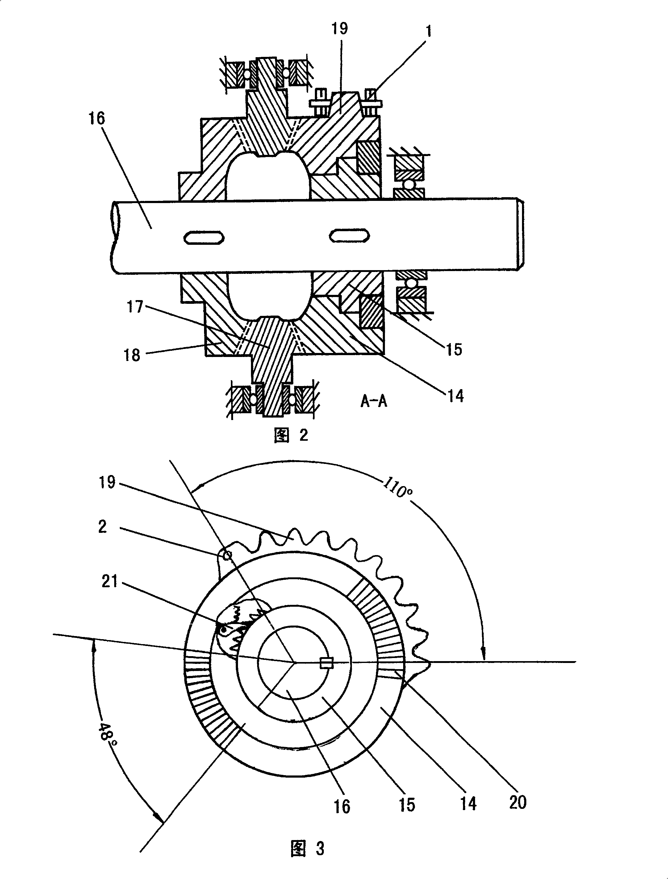
[0022] As shown in Fig. 1, it is a schematic diagram of the front view of the combination of the single cylinder and the main shaft in the present invention. The structure of the present invention is as follows: it is made up of fuel ignition system and camshaft, and one or four main transmission wheel assemblies and corresponding power cylinder 6 with main transmission wheel assembly are fixedly installed on the main shaft 16, and described main transmission wheel assembly passes through One end of the chain 1 fixed on the chain holder 2 is hinged with the piston rod 10 protruding from the power cylinder 6, and the power cylinder 6 is lined with a cylinder sleeve made of wear-resistant material, which is integrated with the piston rod 10 and has a piston ring The piston 12 of 7, one end is the cylinder head A5 that is provi...


PUM


Abstract

The invention discloses a motor, especially providing a petrol motor with reasonable operation, energy-saving, high exchange efficiency and non-side force component. It is formed by a fuel fire system and a boss axle, wherein, it comprises at least one main axle of main transmission wheel element and a horizontal power cylinder relative to the main transmission wheel element; and one end of piston rod of power cylinder is hinged with the chain on the edge of main transmission wheel element. Compared with present technique, it has more reasonable operation of piston, non-side force component, less abrasion between sleeve and cylinder, and prolonged maintenance period. The tension arm for transmitting torque to the main axle is always in the longest position without dead point to improve the power exchange efficiency, save energy, simplify producing process, and reduce cost. The invention can apply variable fuels as mechanical motor.

Description

technical field [0001] The invention relates to an engine, in particular to a gasoline engine with reasonable movement, energy saving, high conversion efficiency and no lateral force component. Background technique [0002] As we all know, the power of the current engine is transmitted by the rotational torque of the crankshaft, and the force obtained by the crankshaft comes from the piston connecting rod mechanism. When the crank is in a vertical state, the length of the torque arm is zero. Only when the crankshaft rotates 90°, the crankshaft’s moment arm is the longest. Therefore, the conversion efficiency of the force on the piston connecting rod to the crankshaft and then to the crankshaft is less than 0.5 , when the conversion efficiency reaches 1 or close to 1, it is highly efficient, and it is also the direction people are pursuing. And the current engine is difficult to clean the exhaust gas when the exhaust gas is exhausted. [0003] In addition, due to the moveme...

Claims


Application Information

Patent Timeline
Patent Type & Authority Patents(China)
IPC IPC(8): F02B75/40F02B67/06F02F1/42F01L1/34F02F1/00
Inventor 李鱼飞
Owner 李鱼飞
Why Eureka
Try Eureka