Grain drying device

A grain drying and hot air technology, applied in heating devices, drying solid materials, heating to dry solid materials, etc., can solve the problems of unit energy consumption, drying efficiency, clean and hygienic defects, large heat transfer coefficient, and low drying efficiency. Superior drying performance, reduced contamination, and simple structure

Inactive Publication Date: 2009-07-15
CHINA AGRI UNIV
View PDF6 Cites 2 Cited by
  • Summary
  • Abstract
  • Description
  • Claims
  • Application Information

AI Technical Summary

Problems solved by technology

Traditional grain drying often adopts mechanical hot air drying, which has long drying time, high energy consumption, and easy pollution. After drying, the grain quality is low, and heat damage often occurs. When drying rice, it will also cause a high waist burst rate. , poor palatability, low rice yield and other shortcomings
[0003] The far-infrared radiation drying method transmits energy in the form of electromagnetic waves, which has the advantages of direct and rapid heating, clean and hygienic, energy-saving and time-saving, and small footprint, but has the disadvantages of large energy consumption and electric heating.
As a widely used traditional drying method, the hot air convection drying method uses air as the heating medium to contact the grain for heat and mass transfer. It has the advantages of uniform drying, mature technology, and extensive heat sources, but there are low drying efficiency and easy pollution. insufficient
The pulsating burner can produce a dry heat source with high-temperature clean pulsating airflow. It has the advantages of high combustion intensity, complete combustion, low emission pollution, high thermal efficiency and large heat transfer coefficient, but has the disadvantage of high working noise.
[0004] Side-heating infrared radiation and hot air convection grain drying technology is a new type of grain drying machine jointly developed by Japan Agricultural Association and four grain dryer manufacturers after 2000. equipment, but because the machine uses 0# diesel burner as the dry heat source, the diesel burner with complex structure has high manufacturing cost, incomplete combustion, and oily smoke
And because diesel is used as fuel, the airflow used for convective drying will inevitably be polluted by diesel to a certain extent, so this kind of equipment has defects in unit energy consumption, drying efficiency, cleanliness and other indicators.

Method used


Image

  • Grain drying device
  • Grain drying device
  • Grain drying device

Examples


Embodiment Construction

[0029] The specific implementation of the grain drying device of the present invention will be further described in detail below in conjunction with the accompanying drawings, but it is not used to limit the protection scope of the present invention.

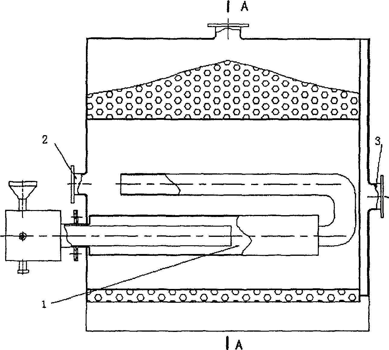
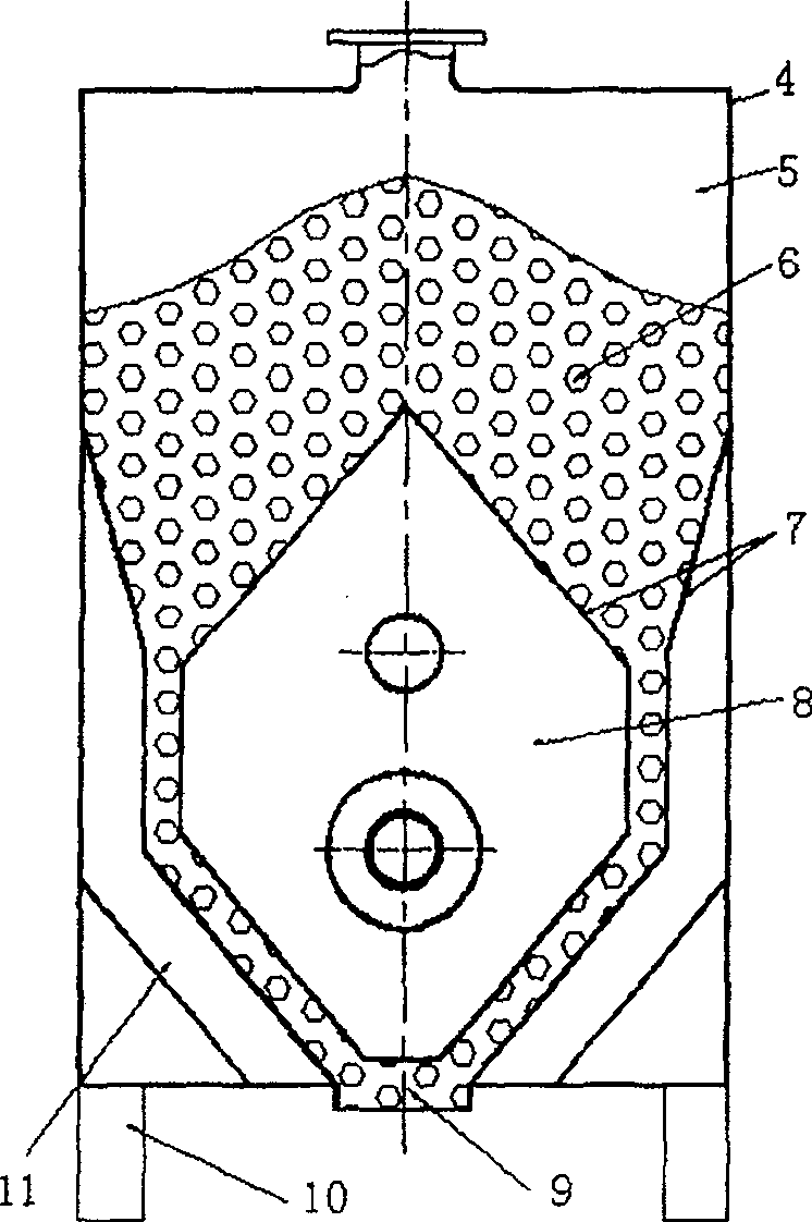
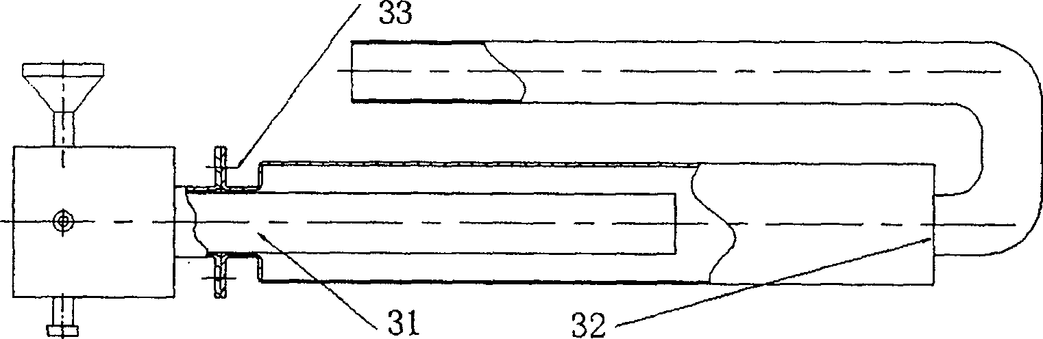
[0030] such as 1 and figure 2 As shown, the grain drying device of the present invention includes a heat source generator 1, an air inlet 2, an air inlet 3, a casing 4, a feed bin 5, an orifice 7, a hot air radiation bin 8, a discharge port 9, a base 10 and Exhaust storehouse 11. Wherein the box body 4 is fixed on the base 10, and the orifice plate 7 divides the inner space of the box body 4 into a feed bin 5, a hot air radiation bin 8 and an exhaust bin 11; the air inlet 2 is fixed on the left side of the box body 4 With sub-infrared radiation tube 54 (see Figure 5 ) corresponding to the nozzle, and communicated with the hot air radiation warehouse 8, the air introduction port 3 is fixed on the right side of the box body 4 ...


PUM


Abstract

The invention provides a device for grain drying, which mainly includes a hot air radiation bin and a heat source generator located therein, wherein the heat source generator includes a pulse burner and an infrared radiator. The grain drying device of the invention combines pulsating combustion, infrared radiation and hot air convection to simultaneously heat the grains by side-heating infrared radiation and high-frequency hot air convection with high temperature and high frequency oscillating airflow. Compared with the traditional method, the device has low fuel consumption rate and low power consumption rate, and the drying precipitation rate is increased, which greatly improves the drying efficiency.

Description

technical field [0001] The present invention relates to a drying device, more specifically, relates to a grain drying device which adopts a pulse burner as an initial heat source and combines far-infrared radiation and convection heating. Background technique [0002] Grain drying research is an important research content in the field of agricultural product processing, and has a very broad application market and prospects. Traditional grain drying often adopts mechanical hot air drying, which has long drying time, high energy consumption, and easy pollution. After drying, the grain quality is low, and heat damage often occurs. When drying rice, it will also cause a high waist burst rate. , Poor palatability, low rice yield and other shortcomings. [0003] The far-infrared radiation drying method transmits energy in the form of electromagnetic waves, which has the advantages of direct and rapid heating, clean and hygienic, energy-saving and time-saving, and small footprint,...

Claims


Application Information

Patent Timeline
Patent Type & Authority Patents(China)
IPC IPC(8): F26B23/00F26B3/30
Inventor 刘相东杨彬彬袁越锦
Owner CHINA AGRI UNIV
Why Eureka
Try Eureka