
Supercritical pressure steam pouring furnace

A steam injection boiler and supercritical technology, applied in steam boilers, forced flow steam boilers, steam generation, etc., can solve problems such as heat transfer deterioration, working fluid temperature cannot be further increased, and supercritical pressure cannot be reached, achieving improved The effect of safe operation on reliability

Active Publication Date: 2009-11-11
THE EIGHTH CONSTR COMPANY OF CNPC
View PDF6 Cites 0 Cited by
  • Summary
  • Abstract
  • Description
  • Claims
  • Application Information

AI Technical Summary

Problems solved by technology

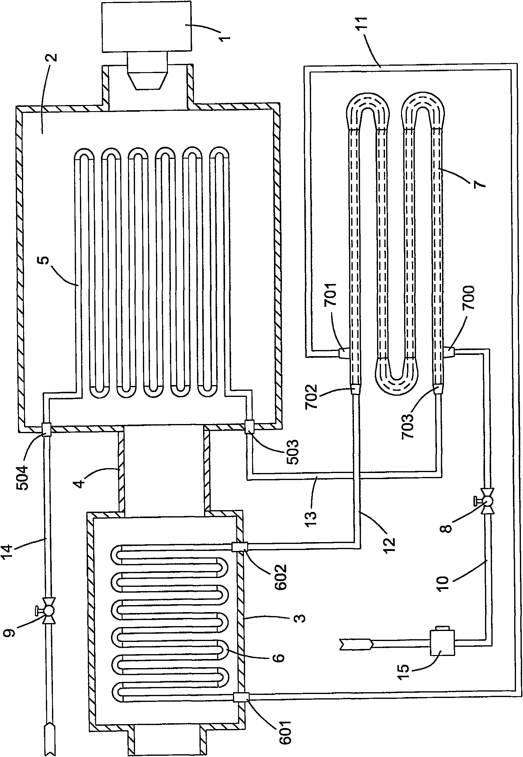
[0008] In the boiler with the above structure, the water vapor piping system is relatively simple, and the radiant tube bundle is a single tube bundle. The primary heating and final heating of the steam are both completed by the radiant tube bundle. The radiant tube bundle is located in the furnace and is directly baked by the burner flame. The load is high, and the flow rate of the working fluid is small, and the heat transfer will deteriorate, so that the temperature of the working fluid cannot be further increased.
Therefore, the steam pressure generated by the existing boiler can only reach the subcritical 21 MPa, and cannot reach the supercritical pressure, which cannot meet the needs of the development of heavy oil production to deeper fields. At present, many oil fields have considerable reserves of ultra-deep heavy oil. Steam at subcritical pressure cannot be injected, and this part of the reserve has not been able to be effectively developed and utilized

Method used


Image

  • Supercritical pressure steam pouring furnace
  • Supercritical pressure steam pouring furnace
  • Supercritical pressure steam pouring furnace

Examples


Embodiment Construction

[0034] 1 burner 2 furnace 3 flue 4 connecting pipe

[0035] 5 radiation tube bundle 503 entrance 504 exit

[0036] 6 convection tube bundle 601 inlet 602 outlet 7 heat exchanger

[0037] 700 shell entrance 701 shell exit

[0038] 702 Tube entrance 703 Tube exit

[0039] 8 valves 9 valves 10 water supply pipe

[0040] 11 water pipe 12 water pipe 13 water pipe

[0041] 14 Steam discharge pipe 15 Water pump 16 Water pump

[0042] 17 chimney 18 valve 19 valve 20 trailer

[0043] 21 burner 22 furnace 23 flue 24 connecting pipe

[0044] 25 first radiant tube bundle 252 entrance 253 exit

[0045] 26 first convection tube bundle 261 inlet 262 outlet 27 heat exchanger

[0046] 270 shell entrance 271 shell exit

[0047] 273 Tube entrance 274 Tube exit

[0048] 28 second radiant tube bundle 284 entrance 285 exit

[0049] 29 second convection tube bundle 295 inlet 296 outlet 30 water supply pipe

[0050] 31 Pipeline 1 32 Pipeline 2 33 Pipeline 3 34 Pipeline 4

[0051] 35 No. ...


PUM


Abstract

A supercritical pressure steam injection boiler has a burner, a furnace, a flue, and a water supply pipe. First and second radiant tube bundles are arranged in the furnace, first and second convective tube bundles are arranged in the flue, and the water supply pipe and heat exchange The shell-side inlet of the heat exchanger is connected, the shell-side outlet of the heat exchanger is connected with the inlet of the first convection tube bank through the No. 1 pipe, the outlet of the first convection tube bank is connected with the inlet of the first radiant tube bank through the No. The outlet of the heat exchanger communicates with the tube-side inlet of the heat exchanger through No. 3 pipe, the tube-side outlet of the heat exchanger communicates with the inlet of the second radiant tube bundle through No. The inlet of the tube bundle is connected, and the outlet of the second convection tube bundle is connected with the steam discharge pipe; the invention moves the tube bundle heated by the final stage of steam from the radiation section to the convection section, avoiding the deterioration of heat transfer, and the steam pressure can reach 26MPa, solving the problem of high-pressure deep well The problem of difficulty in mining block and super-heavy oil block.

Description

technical field [0001] The invention relates to special equipment for thermally exploiting deep well heavy oil in the petroleum industry, in particular to a steam injection boiler. Background technique [0002] The steam injection boiler is the core equipment for heavy oil exploitation in the oil field. It injects the high-pressure steam into the oil well to heat the crude oil in the oil layer to reduce the viscosity of the heavy oil and increase the fluidity of the heavy oil, thereby improving the recovery of deep well heavy oil. Rate. [0003] The structure of the existing steam injection boiler is as follows: figure 1 As shown: it is mainly composed of a burner 1, a furnace 2, and a flue 3. The furnace 2 and the flue 3 are connected through a connecting pipe 4. The furnace 2 is the heat radiation section of the boiler, and the flue 3 is the heat convection section of the boiler. Radiant tube bundles 5 are arranged in the furnace 2, convective tube bundles 6 are arranged...

Claims


Application Information

Patent Timeline
Patent Type & Authority Patents(China)
IPC IPC(8): F22B3/08F22B29/06E21B43/24
Inventor 韩建荒孙新利李亚奇樊海轩缪素景苏广文王建和徐敏
Owner THE EIGHTH CONSTR COMPANY OF CNPC
Learn More