Polymer thin-film solar cell with laminated structure

A technology of solar cells and stacked structures, applied in circuits, photovoltaic power generation, electrical components, etc., can solve problems such as narrow absorption bands, energy loss, and low light absorption efficiency, and achieve the effect of improving energy conversion efficiency and improving matching

Inactive Publication Date: 2010-02-03
CHANGZHOU INST OF ENERGY STORAGE MATERIALS &DEVICES
View PDF5 Cites 1 Cited by
  • Summary
  • Abstract
  • Description
  • Claims
  • Application Information

AI Technical Summary

Problems solved by technology

However, conjugated polymer materials usually have narrow absorption bands that do not match the spectrum of sunlight, resulting in less efficient absorption of light.
In addition, even if the photons with energy higher than the bandgap of the conjugated polymer can be completely absorbed, the excitons in the highly excited state have to release heat to return to the lowest excited state to achieve charge separation, so a lot of energy is lost

Method used


Image

  • Polymer thin-film solar cell with laminated structure
  • Polymer thin-film solar cell with laminated structure
  • Polymer thin-film solar cell with laminated structure

Examples


Embodiment 1

[0061] Using chlorobenzene as a solvent, the P3HT:PCBM mixed solution with a concentration of 18 mg / ml and PCBM accounting for 44% of the total mass was heated and stirred at 60°C for 3 hours, then stopped heating and continued to stir for 12 hours.

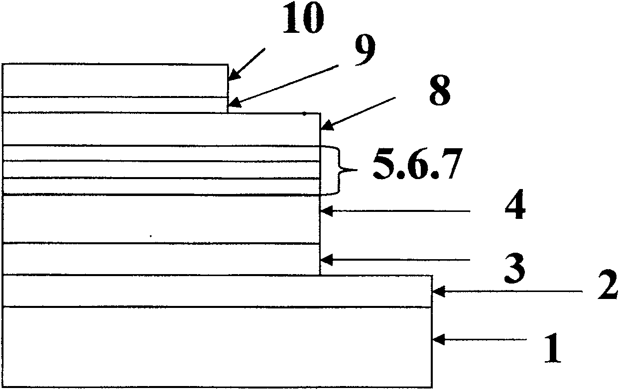
[0062] The ITO anode layer 2 and the glass substrate 1 form an ITO conductive glass, and the etched strip-shaped ITO conductive glass with a certain width is cleaned and dried. Place the clean ITO glass on the bracket of the spin coating machine, apply the PEDOT:PSS solution evenly to the entire sheet through a 0.45 micron filter head, and rotate at a speed of 3000 rpm for one minute to make the PEDOT:PSS on the ITO surface A thin film with a thickness of 40 nanometers was formed as the anode modification layer 3 and heated in an oven at 120° C. for 30 minutes.

[0063] Transfer the baked ITO substrate coated with PEDOT:PSS to the glove box, place it on the spin coater bracket after the substrate is cooled, and evenly coat the st...

Embodiment 2

[0068] With chlorobenzene as solvent, the concentration is respectively 10 mg / ml and 20 mg / ml, and the quality of PCBM accounts for 40% and 80% of the total mass of P3HT:PCBM mixed solution heated and stirred at 60 degrees for 3 hours, stop heating and continue Stir for 12 hours.

[0069] The ITO anode layer 2 and the glass substrate 1 form an ITO conductive glass, and the etched strip-shaped ITO conductive glass with a certain width is cleaned and dried. Place the clean ITO glass on the bracket of the spin coating machine, apply the PEDOT:PSS solution evenly to the entire sheet through a 0.45 micron filter head, and rotate at a speed of 5000 rpm for one minute to make the PEDOT:PSS on the ITO surface A thin film with a thickness of 20 nanometers was formed as the anode modification layer 3 and heated in an oven at 120° C. for 30 minutes.

[0070] The baked ITO substrate coated with PEDOT:PSS is transferred to the glove box, and after the substrate is cooled, it is placed on ...

Embodiment 3

[0075] With chlorobenzene as solvent, the concentration is respectively 10 mg / ml and 20 mg / ml, and the quality of PCBM accounts for 40% and 80% of the total mass of P3HT:PCBM mixed solution heated and stirred at 60 degrees for 3 hours, stop heating and continue Stir for 12 hours.

[0076] The ITO anode layer 2 and the glass substrate 1 form an ITO conductive glass, and the etched strip-shaped ITO conductive glass with a certain width is cleaned and dried. Place the clean ITO glass on the bracket of the spin coating machine, apply the PEDOT:PSS solution evenly to the entire sheet through a 0.45 micron filter head, and rotate at a speed of 1200 rpm for one minute to make the PEDOT:PSS on the ITO surface A thin film with a thickness of 100 nanometers was formed as the anode modification layer 3 and heated in an oven at 120° C. for 30 minutes.

[0077] The baked ITO substrate coated with PEDOT:PSS is transferred to the glove box, and after the substrate is cooled, it is placed on...


PUM


Abstract

The invention discloses a laminated polymer solar cell, which comprises a base plate, an anode layer, an anode modification layer, a first active layer, a cathode modification layer, a cathode layer and an intermediate electrode consisting of an electronic transport layer, a metal layer and a hole transport layer, wherein the intermediate electrode consists of an n-type metallic oxide electron transport layer and a p-type metallic oxide hole transport layer which are high in light transmittance. A thin layer of metal is inserted between the two metallic oxides and the effective combination ofelectrons and holes. The active layers of up and down two sub-cells of the laminated polymer solar cell are mixtures of identical or different conjugated polymers. The open circuit voltage of the laminated solar cell is the sum of the open circuit voltages of the up and down two sub-cells, so the serial connection of polymer photovoltaic cells is realized. The combined intermediated electrode structure can be wildly used in laminated devices with active layers made of conjugated polymers of different light absorption ranges, so as to well match the light absorption of the whole cell with the solar spectrum and improve the energy conversion rate.

Description

technical field [0001] The invention relates to a laminated structure polymer thin film solar cell. Background technique [0002] Organic / conjugated polymer thin-film solar cells have incomparable advantages over inorganic solar cells, such as: can be prepared on a soft substrate; industrialized mass production can be realized in a continuous printing process; compared with inorganic silicon cells, the production cost can be reduced Significantly lower; has important ecological and economic advantages. However, conjugated polymer materials typically have narrow absorption bands that do not match the spectrum of sunlight, resulting in low light absorption efficiency. In addition, even if the photons with energy higher than the bandgap of the conjugated polymer can be completely absorbed, the excitons in the highly excited state have to release heat to return to the lowest excited state to achieve charge separation, so a lot of energy is lost. Therefore, the use of conjugate...

Claims


Application Information

Patent Timeline
Patent Type & Authority Patents(China)
IPC IPC(8): H01L51/42H01L51/44H01L51/46
CPCY02E10/549
Inventor 谢志元郭晓阳王利祥刘凤敏
Owner CHANGZHOU INST OF ENERGY STORAGE MATERIALS &DEVICES
Why Eureka
Try Eureka