Method for implementing optical virtual private network in passive optical network

A passive optical network and virtual private network technology, applied in the field of realizing optical virtual private network, can solve the problems of increasing system cost, unable to support simultaneous transmission of VPN internal services and transmission of non-VPN services, etc.

Inactive Publication Date: 2010-03-24
SHANGHAI JIAOTONG UNIV
View PDF3 Cites 0 Cited by
  • Summary
  • Abstract
  • Description
  • Claims
  • Application Information

AI Technical Summary

Problems solved by technology

The disadvantage of this technology is that each ONU needs two transmitters and two receivers, which greatly increases the cost of the system
It is also found in the retrieval that among the prior art supporting communication within the ONU group, the article "A Packet-Switched Waveband-selective PON Enabling Optical Internetworking among ONUs" published in European Conference on Optical Communication 2005 (2005 European Optical Communication Conference) A technology is disclosed in "Band Selective Passive Optical Network for Packet Switching for Optical Interconnection between Network Units)", that is, a fast adjustable reflector is placed at the end of the optical line to reflect the data packets inside the VPN, However, this solution cannot support the simultaneous sending of VPN internal services and the transmission of non-VPN services

Method used


Image

  • Method for implementing optical virtual private network in passive optical network
  • Method for implementing optical virtual private network in passive optical network
  • Method for implementing optical virtual private network in passive optical network

Examples


Embodiment Construction

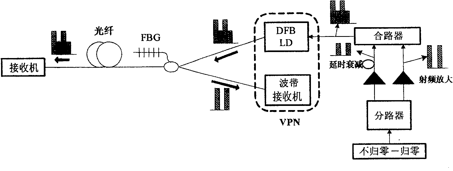
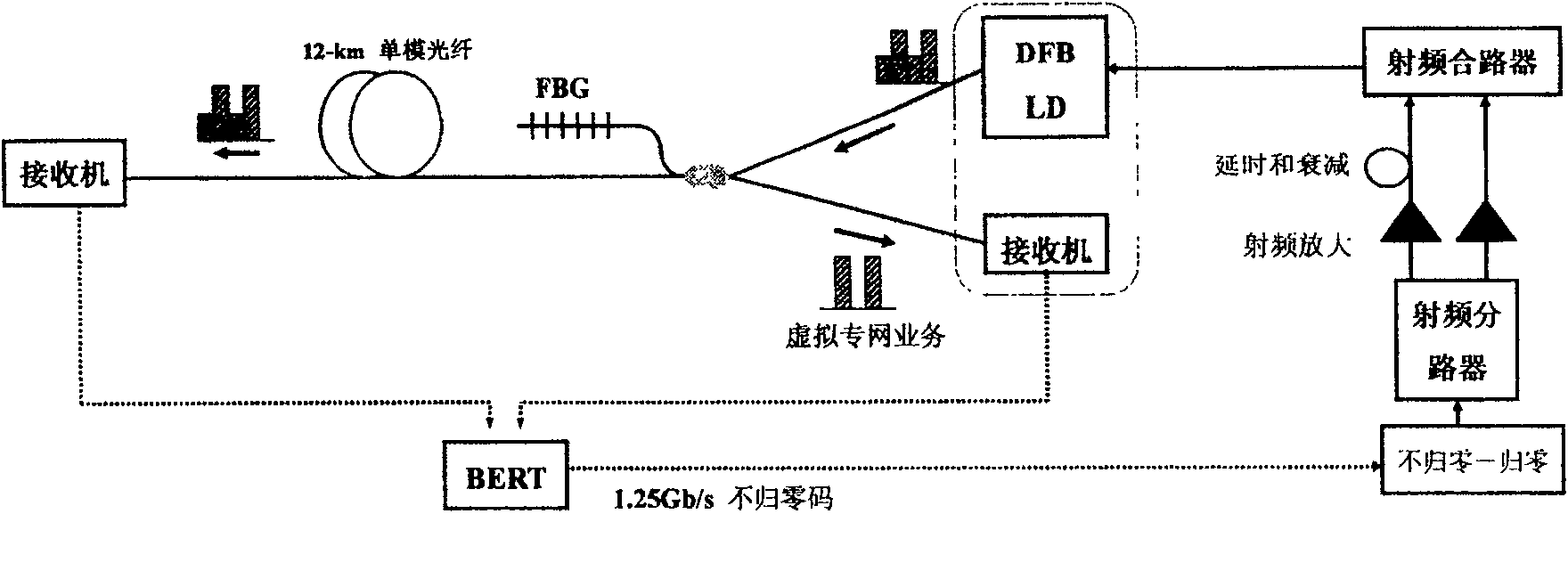
[0020] Such as figure 1 As shown, the generated pseudo-random sequence is modulated into a return-to-zero code (RZ) with a duty cycle of 50% through an external circuit. The RZ signal is divided into two paths through the radio frequency splitter, and the two paths of signals are amplified through the radio frequency amplifier. Delay and attenuate one of the signals to produce a different phase and amplitude from the other signal. Then the two signals are combined and injected into the distributed feedback Bragg laser diode. Since the two branch signals have different amplitudes, a TDM-FDM signal is generated. After the signal passes through the optical splitter, one of them is transmitted to the Bragg reflection grating, and the signal corresponding to the VPN internal service is reflected. The other signal goes through the optical fiber to the receiver at the end of the optical line. The DFB LD shown in Figure (1) is located in the transmitter of an optical network unit ...


PUM


Abstract

The invention relates to a method for realizing optical virtual network in the passive optical network, which comprises: 1, modulating the VPN internal service and the non-VPN internal service, in theoptical network unit; 2, processing time division multiple access in the coupler of optical network unit between groups of signals; 3, injecting the signal into the feedback Prague laser diode; 4, when the signal reaches the optical divider, one part is distributed to the narrow band reflector which can recognize and reflect the signal relative to the VPN internal service according to the frequency, and the VPN internal ONU via the wave band receiver receives returned VPN internal signal; when another part reaches the terminal of optical line, the wide band receiver according to the frequencyrecognizes and receives the signal relative to the non-VPN internal service. The inventive TDM-FDM format avoids the expensive modulator, while the drive signal can be attained easily, and each ONU needs only one couple of sender and receiver.

Description

technical field [0001] The present invention relates to a method in the technical field of optical fiber communication, specifically, a method for realizing an optical virtual private network in a passive optical network using a time division multiplexing-frequency division multiplexing (TDM-FDM) modulation format . Background technique [0002] Passive Optical Network (PON) is an economical and future-oriented multi-service user access technology. PON technology is a point-to-multipoint fiber optic access technology, which consists of optical network units and optical line units. It has two wavelength channels: uplink channel and downlink channel. The downlink adopts the TDM broadcasting method, and the uplink adopts the TDMA (Time Division Multiple Access) method, and can be flexibly formed into tree, star, bus and other topological structures. On the other hand, Virtual Private Network (VPN) is a new Internet service that has developed rapidly in recent years. It comp...

Claims


Application Information

Patent Timeline
Patent Type & Authority Patents(China)
IPC IPC(8): H04B10/20H04L12/56H04J14/08H04Q11/00H04L12/46
Inventor 苏翼凯张晶晶胡卫生
Owner SHANGHAI JIAOTONG UNIV
Why Eureka
Try Eureka