
Long range big-push force permanent-magnet brushless linear DC motor

A DC motor and permanent magnet technology, applied in the direction of linear DC motor control, AC motor control, electric components, etc., can solve the problems of aggravating the saturation degree of the inner column magnetic flux density, increasing the leakage flux, increasing the stroke, etc., to achieve the guide Good magnetic properties, high resistivity, and the effect of reducing reverse electromagnetic force

Inactive Publication Date: 2007-08-01
DALIAN JIAOTONG UNIVERSITY
View PDF0 Cites 29 Cited by
  • Summary
  • Abstract
  • Description
  • Claims
  • Application Information

AI Technical Summary

Problems solved by technology

[0004] The commutation of ordinary DC linear motors needs brushes to complete, but the working stroke of brushed DC linear motors should not be too long, regardless of whether they are electric excitation or permanent magnet excitation, and there are contact sparks that interfere with electronic equipment.
The voice coil DC linear motor does not need brushes, but when the length of the moving coil remains unchanged, the axial length of the permanent magnet must be increased to maintain the constant thrust of the motor when the stroke is increased
The longer the magnetic steel, the more magnetic flux will converge to the inner column of the motor, which will intensify the saturation of the inner column magnetic flux density, resulting in increased leakage flux, so it should not be made too long
Long-stroke linear DC motors generally adopt a brushless structure, but due to the alternating air gap flux, to obtain thrust in a certain direction, the direction of the current in the mover coil must be frequently reversed, which increases the complexity of the control circuit

Method used


Image

  • Long range big-push force permanent-magnet brushless linear DC motor
  • Long range big-push force permanent-magnet brushless linear DC motor
  • Long range big-push force permanent-magnet brushless linear DC motor

Examples


Embodiment Construction

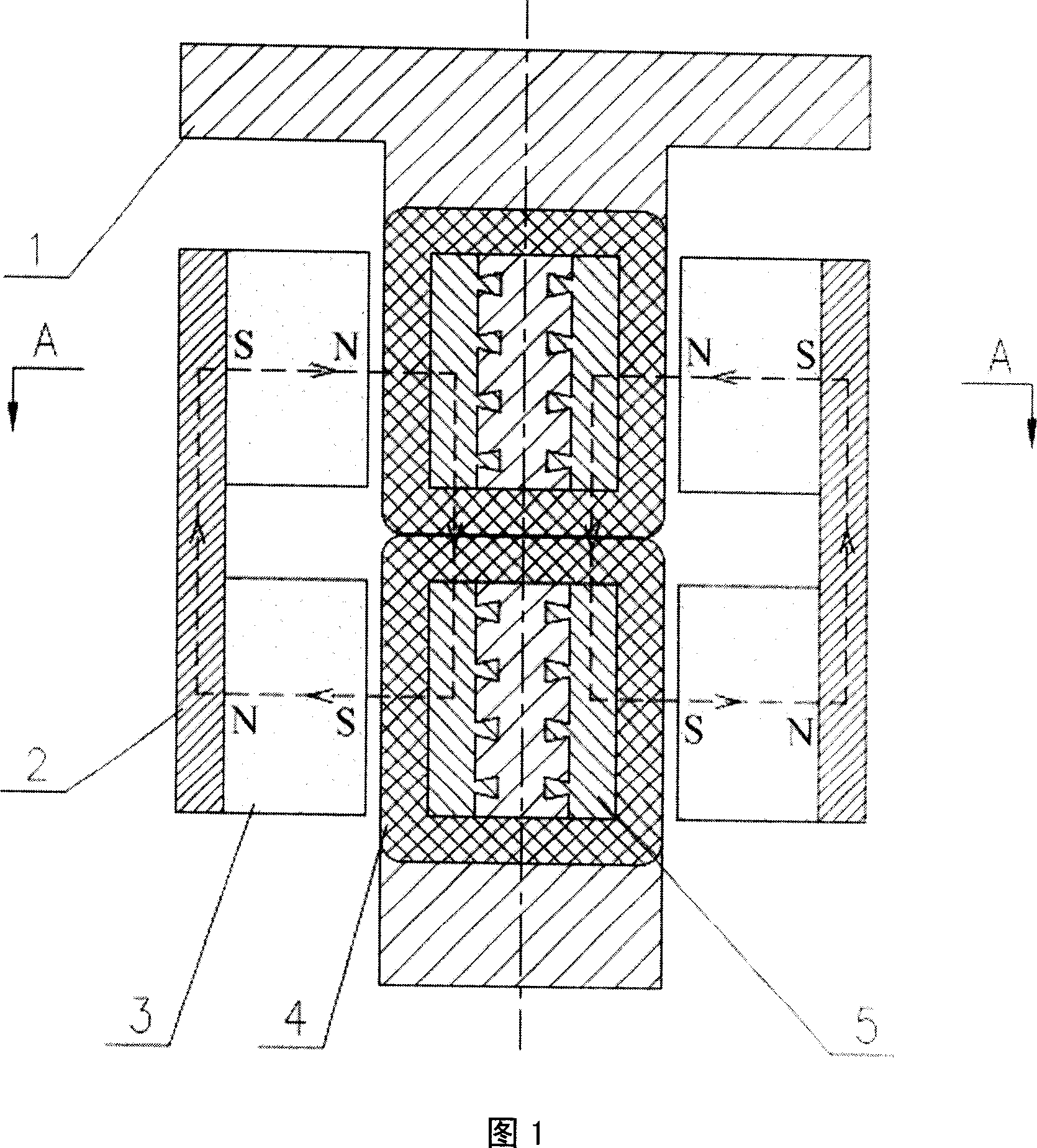
[0023] The driving principle of the long-stroke and high-thrust permanent magnet brushless linear DC motor of the present invention is shown in Figure 6. The wire is placed along the direction perpendicular to the magnetic field. When the wire is passed with current, the wire will be subjected to the electromagnetic force shown in the figure The effect of this electromagnetic force is the thrust of the present invention, and its magnitude can be obtained according to the formula F=NBIL, wherein N is the number of turns of the coil, B is the magnetic field strength, I is the coil current strength, and L is the single-turn coil in the magnetic field effective length in .

[0024] The invention uses a grating detection system to detect the displacement and speed of the motor mover. The specific principle is: the grating detection system outputs two square wave pulse signals with a phase difference of 90°, which are sent to the two QFP pins of the DSP after shaping, and then the ti...


PUM


Abstract

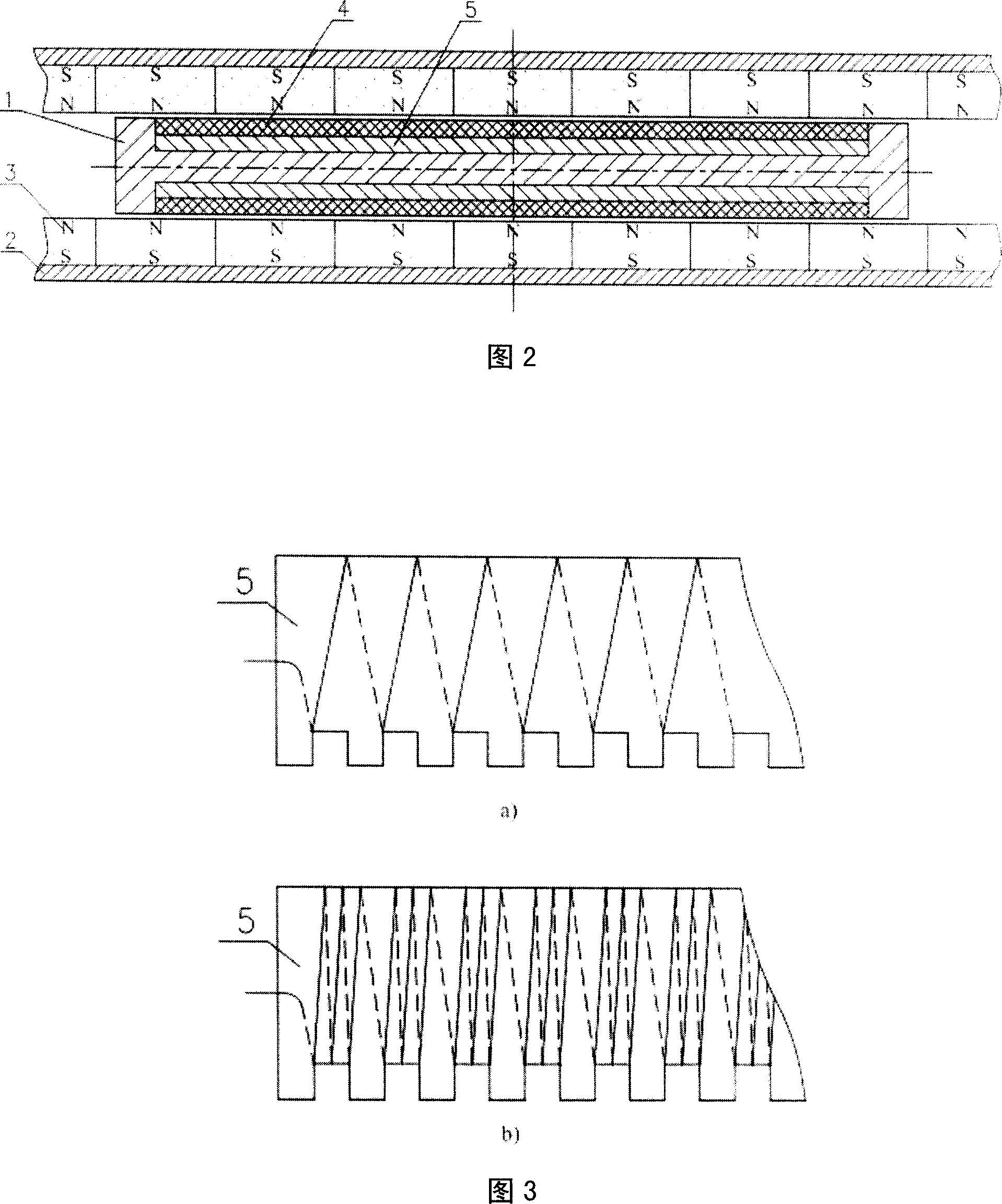
A long journey big thrust permasyn brushless beeline direct electromotor that includes stator part, rotor part and position and speed controlling system of the electromotor. The stator part composes permanent-magnet (3) and magnetic yoke (2), magnetizer (5) is connected with rack (1) via coattail groove structure, and two windings (4) with different direction current circle the magnetizer to form rotor part. The invention adopts the two-sized stator structure to eliminate the single sized magnetic pull, and the thrust is big, journey is long, the weight of rotor is light, without contact running and cost is low, it is fit for common numerical control machine tool feeding system, special numerical control machine tool feeding system which adopts gas floating or magnet floating guiding track and other high speed and high acceleration direct feeding systems.

Description

technical field [0001] The invention relates to a linear DC motor, in particular to a long-stroke and high-thrust permanent-magnet brushless linear DC motor that can realize high-speed and high-acceleration feeding. Special CNC machine tool feed system for guide rails and other linear feed systems that require high speed and high acceleration. Background technique [0002] Evolved from a rotary motor, a linear motor is a device that converts electrical energy directly into linear motion. Corresponding to rotary motors, linear motors include linear induction motors, linear synchronous motors, linear DC motors, and linear stepping motors. [0003] Among them, the linear DC motor adopts DC power supply. Compared with the linear AC motor, its obvious advantages are: high operating efficiency, no problem of low power factor, and convenient and flexible control. The combination of linear DC motor and closed-loop control system can precisely control the displacement, its speed an...

Claims


Application Information

Patent Timeline
IPC IPC(8): H02K41/035H02K1/27H02K1/17H02K1/02H02P25/06H02P6/16H02P6/17H02P7/02
Inventor 葛研军张文跃蒋成勇吴艳波李菊焕王刚军沈强
Owner DALIAN JIAOTONG UNIVERSITY
Learn More