Thermal production well filling vapor and nitrogen foam profile control technique

A technology of nitrogen foam and process method, which is applied in the direction of production fluid, earthwork drilling, wellbore/well components, etc., which can solve the problems of reducing the efficiency and effect of heavy oil thermal recovery, reducing the effective steam sweep area, and decreasing the periodic oil-gas ratio. , to improve the effect of heat insulation, improve the effect of throughput and recovery, and reduce the effect of heat loss

Inactive Publication Date: 2010-05-19
SINOPEC SHENGLI OILFIELD
View PDF3 Cites 0 Cited by
  • Summary
  • Abstract
  • Description
  • Claims
  • Application Information

AI Technical Summary

Problems solved by technology

However, the heterogeneity of heavy oil reservoirs and the characteristics of thermal recovery technology, the deposition of colloid and asphaltene after multiple rounds of huff and puff, and the gravity overriding cause steam channeling in high-permeability layers, water channeling, steam channeling, and steam channeling along the high The breakthrough of the permeable zone makes the steam sweep coefficient small and greatly reduces the effective steam sweep area; after multiple rounds of huff and puff, the pressure drop of the formation increases, which is affected by the invasion of edge water and bottom water, which reduces the benefit and effect of heavy oil thermal recovery
[0003] The throughput cycle of Gudao Oilfield reached 430 days, but due to the increase of throughput rounds, the cycle oil-gas ratio decreased, resulting in a sharp increase in oil well water cut

Method used


Image

  • Thermal production well filling vapor and nitrogen foam profile control technique
  • Thermal production well filling vapor and nitrogen foam profile control technique
  • Thermal production well filling vapor and nitrogen foam profile control technique

Examples


Embodiment Construction

[0021] 1. Performance requirements of foaming agent

[0022] 2. Adaptation conditions

[0023] (1) The reservoir has strong heterogeneity. Since foam is mainly produced in the large pores of the sand layer, oil layers with higher permeability are selected;

[0024] (2) Blocks with active side and bottom water and heavy oil wells with integrated water content> 90%.

[0025] (3) After multiple huffs and puffs, a steam channel is formed, and the remaining oil is abundant within the steam heating radius;

[0026] (4) According to the test, when the steam flooding residual oil saturation (18.2%) is below, it starts to have a higher plugging capacity, so oil wells with low oil saturation and high permeability strips are selected;

[0027] (5) The thickness of the oil layer ≥ 5 meters;

[0028] (6) The downhole casing is intact.

[0029] 3. Nitrogen source and injection method

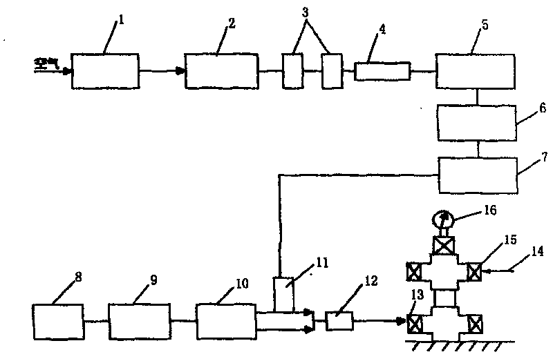
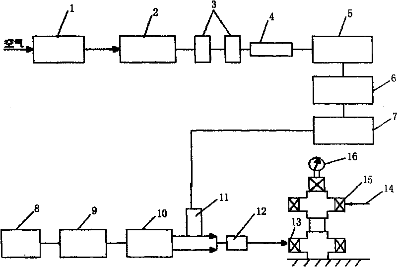
[0030] The process of using membrane air separation nitrogen car to produce nitrogen is as follows figure 1 Shown.

[003...


PUM


Abstract

The invention relates to a thermal developing well pouring steam nitrogen foam adjusting method comprising steam, nitrogen and foaming agent pouring method and nitrogen generating pouring method, wherein the steam is poured via an oil tube, the nitrogen and the foaming agent are poured in via a muffle, while the mass ratio between the foaming agent, steam is 1:250-500, the mass ratio between the nitrogen and the stem is 50-80:1, the pouring speed is steam at 10-13t / h, foaming agent at 0.1-0.5t / h, and nitrogen at 900-1000Nm3 / h. And the invention uses four-section plug pouring process, while thefirst section plug pours nitrogen via the muffle for 12h at 900-1000Nm3 / h, the second section plug pours the steam via the oil tube for 24h at 10-13t / h, and the third section plug pours steam via theoil tube and pours nitrogen and foaming agent via the muffle at 10-13t / h, 900-1000Nm3 / h, and 0.1-0.5t / h for 2h, the fourth section plug stops pouring foaming agent and holds the pouring speed of thenitrogen and the steam for 12h, repeats the steps of four section plugs until preset demand, closes the well, then opens well to produce.

Description

1. Technical Field [0001] The invention relates to a nitrogen foam profile control technique suitable for steam injection of steam stimulation wells in heavy oil oil fields, and is suitable for profile control applications of high water-cut wells in heavy oil steam stimulation oilfields, in particular to a thermal recovery A well steam injection nitrogen foam profile control process belongs to the field of petroleum development. 2. Background technology [0002] More than one third of my country’s crude oil reserves belong to heavy oil reservoirs. Due to the physical properties of heavy oil (high underground viscosity, poor fluidity, and high content of colloid and asphaltene), thermal recovery is the main technology for the development of heavy oil reservoirs. . The Gudao Oilfield has also implemented thermal recovery and development for heavy oil reservoirs mainly based on steam stimulation since 1992. Since 1996, the annual oil production has been stable at 50×10. 4 t or more,...

Claims


Application Information

Patent Timeline
Patent Type & Authority Patents(China)
IPC IPC(8): E21B43/24
Inventor 曹正权陈辉姜娜韩鹏张岩李葵英
Owner SINOPEC SHENGLI OILFIELD
Why Eureka
Try Eureka