Conjugated imaging-based multi-deformable lens series combining wavefront corrector

A wavefront corrector and multi-deformation technology, applied in the direction of instruments, optical components, optics, etc., can solve the problems of increasing constraints, the maximum stroke and spatial resolution of deformable mirrors cannot be improved at the same time, and the waste of light energy, etc., to achieve Avoid manufacturing, realize simplicity and convenience, and increase the effect of driving stroke

Inactive Publication Date: 2007-08-22
INST OF OPTICS & ELECTRONICS - CHINESE ACAD OF SCI
View PDF0 Cites 10 Cited by
  • Summary
  • Abstract
  • Description
  • Claims
  • Application Information

AI Technical Summary

Problems solved by technology

However, at present, the further improvement of the deformation of the main types of deformable mirrors is restricted by many factors. For example, in a continuous surface discrete actuated deformable mirror (Bimorph DM, PZT DM) of a certain caliber, limited by the mirror material, single actuation The improvement of the deformation amount of the deformable mirror and the increase of the number of actuators are a pair of contradictory factors. The reduction of the distance between the actuators will increase the mutual restriction on the deformation, which means that the maximum travel and space of the deformable mirror The resolution cannot be improved at the same time; for the thin film deformable mirror (MMDM) based on MEMS technology, due to the limitation of the construction process and the phenomenon of electrostatic pull-in, the diameter of the thin film deformable mirror is limited and the utilization rate of the deformation stroke is only 2 / 3. Its maximum deformation is generally 2 to 3 μm; the deformation of liquid crystal deformable mirror (LCDM) depends on the birefringence effect of the material, and its stroke is generally less than 1 μm
[0004] Robert H.Webb et al. proposed to amplify the effective stroke by increasing the number of times the light wave passes through the deformable mirror (“Stroke amplifier for deformable mirrors”, Appl. big waste

Method used


Image

  • Conjugated imaging-based multi-deformable lens series combining wavefront corrector
  • Conjugated imaging-based multi-deformable lens series combining wavefront corrector
  • Conjugated imaging-based multi-deformable lens series combining wavefront corrector

Examples


Embodiment Construction

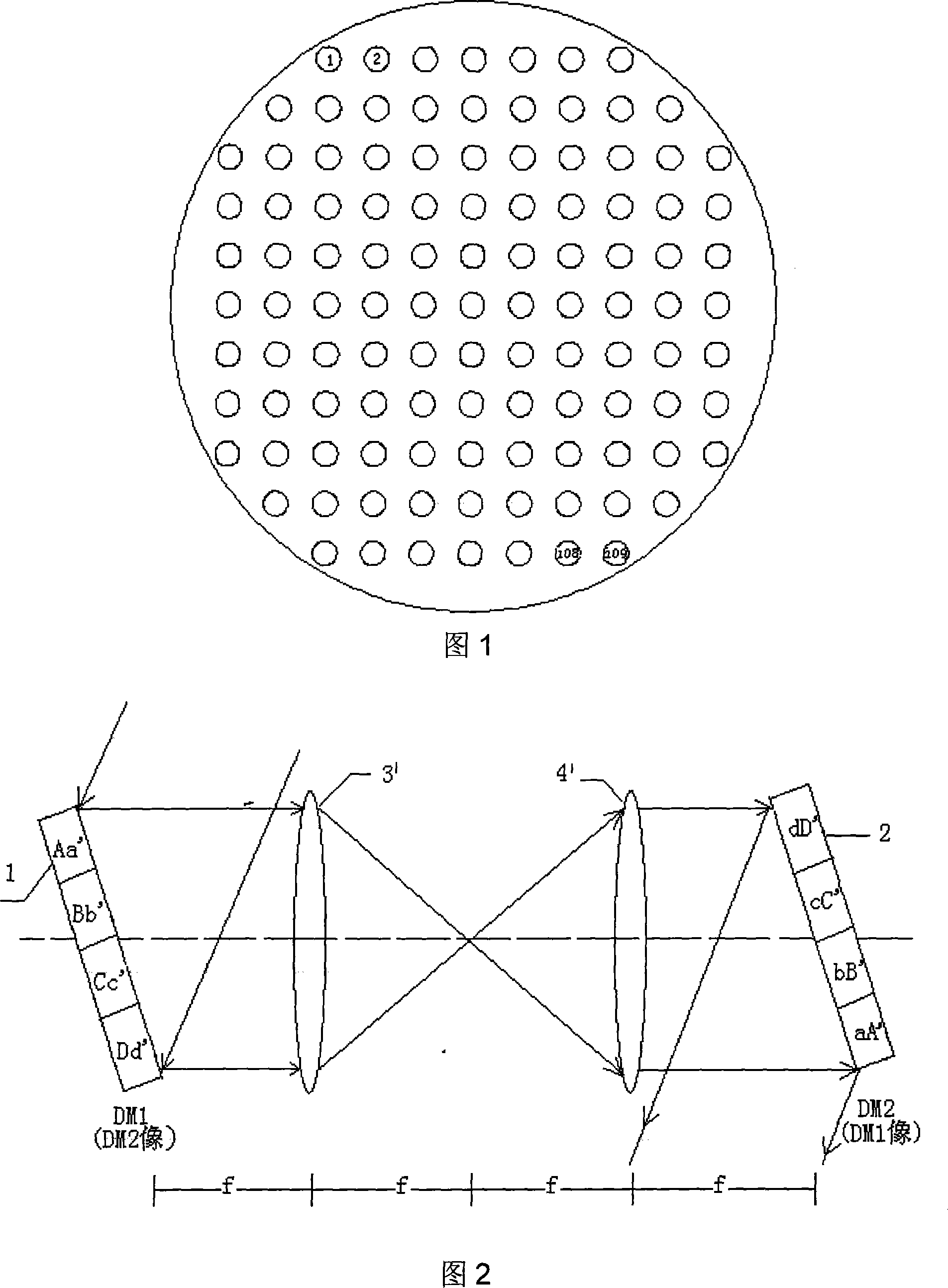
[0022] As shown in Figure 2, in the present invention, two lenses 3', 4' form 4f optical system, deformable mirror 1 and deformable mirror 2 are respectively positioned at the front and rear focal planes of the system, and each other becomes the conjugate position of object image; The spatial positions are correspondingly coincident, and since the system is an inverted image, for a square arrangement of 109 unit deformable mirrors as shown in Figure 1, that is, the No. 1 drive unit of deformable mirror 1 corresponds to No. 109 drive unit of deformable mirror 2, and the 2 Drive unit No. 108 corresponds to drive unit No. 108 of the deformable mirror 2, and so on. Other types of wavefront correctors arranged not as shown in Fig. 1 can be similarly designed. Each pair of drivers (such as drive unit No. 1 of the deformable mirror 1 and drive unit No. 109 of the deformable mirror 2) is used as an overall control unit in the system.

[0023] As shown in Figure 2, after the wavefront...


PUM


Abstract

The invention is a conjugate imaging-based multi-deformable mirror sires combined wave front corrector, comprising at least two same wave front correctors and corresponding 4f optical system, where the adjacent wave front correctors are interconnected by the 4f optical system to compose a combined wave front corrector and make each wave front corrector located in the optical conjugate imaging position, i.e. each wave front corrector is placed on the front focal surface and rear focal surface of the 4f optical system in order, the wave front corrector can be a deformable mirror using piezoelectric or electrostrictive ceramic as driver and separately driving continuous mirror surface, or a double-voltage deformable mirror, a deformable mirror made by microelectronic mechanical system (MEMS) technique, etc; the 4f optical system adopts a lens-composed refracting system or a reflecting system composed of off-axis parabolic mirror. And the invention has simple structure, high light energy utilization ratio, and can effectively increase wave front correction travel and provides an easy-to-implement method for improving the wave front correcting effect of the self-adapting optical system by using the existing deformable mirror manufacturing technique.

Description

technical field [0001] The invention relates to a wavefront corrector for an adaptive optics system, in particular to a conjugate imaging-based multi-deformable mirror series combined wavefront corrector. Background technique [0002] Wavefront phase correction technology is the core technology in adaptive optics, which can usually be realized by using wavefront correction elements that can change the refractive index or optical path length. The application of wavefront correction technology has expanded from astronomy to laser beam shaping, fundus imaging, fast confocal scanning and other fields. In these fields, the demand for deformation of deformable mirrors has also increased significantly. Among them, the wavefront image in the human eye imaging system The poor P-V value can reach more than 20μm. Therefore, for adaptive systems to achieve good wavefront correction in these applications, the deformation of the wavefront corrector must be large enough. [0003] The amo...

Claims


Application Information

Patent Timeline
Patent Type & Authority Applications(China)
IPC IPC(8): G02B26/06
Inventor 饶长辉杨华峰
Owner INST OF OPTICS & ELECTRONICS - CHINESE ACAD OF SCI
Why Eureka
Try Eureka