Transfer belt for image forming apparatus

A technology of an imaging device and a transfer belt, applied in the direction of electrorecording process applying charge pattern, equipment for applying charge pattern electrorecording process, electrorecording technique, etc.

Inactive Publication Date: 2007-09-12
SUMITOMO ELECTRIC FINE POLYMER INC
View PDF1 Cites 9 Cited by
  • Summary
  • Abstract
  • Description
  • Claims
  • Application Information

AI Technical Summary

Problems solved by technology

[0008] However, a transfer belt for an image forming apparatus that suffi

Method used


Image

  • Transfer belt for image forming apparatus
  • Transfer belt for image forming apparatus
  • Transfer belt for image forming apparatus

Examples


Embodiment 1

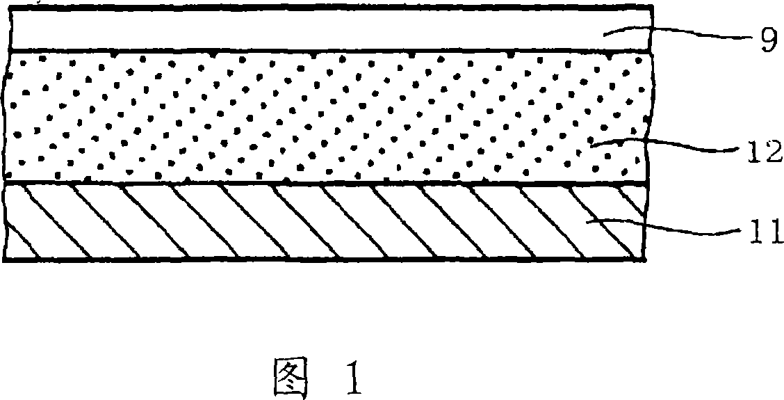
[0156] While rotating the drum mold, polyimide varnish is coated on its outer surface, and then the mold is heated to perform imidation reaction, thereby obtaining a 60 μm thick polyimide covering the periphery of the mold layer (bottom layer). Then adjust the viscosity of aqueous polyurethane (aqueous urethane) to a viscosity of about 10 Pa·s by adding a viscosifier, and perform defoaming, and apply the aqueous polyurethane to the polyimide layer by dip coating . After coating, it was dried at normal temperature to remove water, and annealed at 160° C. to obtain a 200 μm thick polyurethane layer (elastic layer) on the polyimide layer.

[0157] Then, on the polyurethane layer, the THV solution was sprayed under the condition that a thickness of 5 μm after drying and annealing was obtained. It was then dried and annealed at 160°C to form a surface layer, thereby obtaining the transfer belt of the present invention.

Embodiment 2

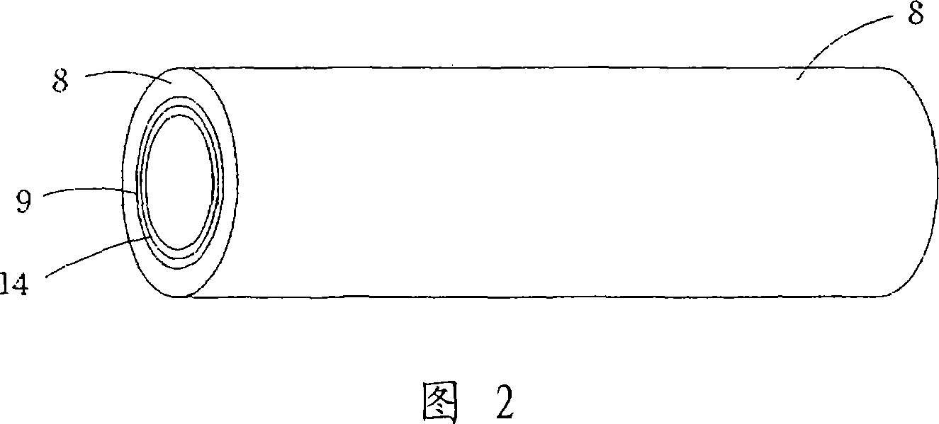
[0159] First, as shown in Figure 2, with 1.76×10 -5 On the inner surface of the steel outer tube 8 with a thermal expansion coefficient of / °C and a mirror-polished inner surface, a dispersion of PTFE (melting point 327°C, thermal decomposition point 400°C) is coated by dip coating, and sintered at 380°C , so as to obtain the surface layer 9.

[0160] THV (melting point: 120° C., thermal decomposition point: 400° C.) was then dissolved in butyl acetate to form a film on surface layer 9 by dip coating and dried to obtain adhesive layer 14 . The adhesive layer 14 is then heated at a temperature above the melting point of PTFE and THV, ie 350° C., thereby bonding the adhesive layer 14 to the skin 9 .

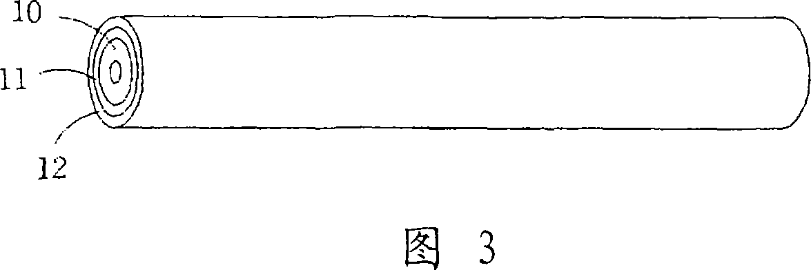
[0161] Then, as shown in FIG. 3 , polyimide subjected to conductive carbon treatment to adjust the volume resistivity was formed into a film on the surface of the drum mold 10 and sintered at 380° C. to obtain the bottom layer 11 .

[0162] Then, water-based polyurethane (melting...

Embodiment 3

[0170] Process in the same manner as in Example 2, except that the amount of THV dissolved in butyl acetate is changed to change the thickness of the adhesive layer 14, and the water-based polyurethane coated on the bottom layer 11 is changed A transfer belt for an image forming device is obtained for ion-conducting polyurethane, which consists of a 200-μm-thick elastic layer (polyurethane) on a 60-μm-thick base layer (polyimide), and a 3-μm-thick adhesive layer (THV) and a 5 μm thick surface layer (PTFE). The ion conductive treatment is performed by dispersing an ionic conductive agent in aqueous polyurethane, and its volume resistivity is adjusted to be 10 times that of the base layer 11 .

[0171] The thus-obtained transfer belt for an image forming apparatus has excellent surface resistivity, toner releasing properties, and non-staining properties. And the volume resistivity of the transfer belt for image forming apparatus is controlled in a stable manner by the elastic l...


PUM

PropertyMeasurementUnit
Volume resistivityaaaaaaaaaa
Thicknessaaaaaaaaaa
Thicknessaaaaaaaaaa

Abstract

Disclosed is a multilayer transfer belt for image-forming devices comprising a base layer (11), an elastic layer (intermediate layer) (12) and a surface layer (9) which has high surface resistivity, excellent toner releasability and excellent antifouling properties. The transfer belt for image-forming devices is characterized in that an elastic layer (12) containing an elastomer and a surface layer (9) composed of a fluorine-containing polymer are arranged on a base layer (11). The elastic layer (12) is preferably made of an ion conductive elastomer. Also disclosed is a transfer belt for image-forming devices further comprising a binder layer (14) between the elastic layer (12) and the surface layer (9) which is characterized in that the melting point of the material constituting the binder layer (14) is not more than the thermal decomposition point of the material constituting the elastic layer (12) and the thermal decomposition point of the material constituting the binder layer (14) is not less than the melting point of the material constituting the surface layer (9).

Description

technical field [0001] The present invention relates to a transfer belt for an image forming apparatus used in a color image forming apparatus (such as a color copier or a color laser printer) using an electrophotographic process for transferring a toner image from a photosensitive drum (photosensitive drum) Print onto transfer material (paper). Background technique [0002] As an image transfer method in a color image forming apparatus such as a color copier or a color laser printer, a method of transferring a toner image formed on a photosensitive drum to a transfer material (paper) by means of a transfer belt for an image forming apparatus gradually became the standard method used. [0003] Fig. 7 is a schematic diagram showing an intermediate transfer method outlining such a transfer method. As shown in FIG. 7 , a toner image is formed on a photosensitive drum 3 by the toner 1 and the developing roller 2 . Since this is a 4-drum tandem system, developing rollers and p...

Claims


Application Information

Patent Timeline
IPC IPC(8): G03G15/16G03G15/20
Inventor 池田一秋冈崎博志羽深正弘
Owner SUMITOMO ELECTRIC FINE POLYMER INC
Why Eureka
Try Eureka