Light etching positioning self assembling filling method

A filling method and self-assembly technology, applied in optics, opto-mechanical equipment, photosensitive materials for opto-mechanical equipment, etc., can solve the problem of limited pattern area, low efficiency, and difficulty in producing nanostructures by electron beam or ion beam lithography. Arraying and other problems to achieve the effect of reducing structural defects, high efficiency and simple production

Inactive Publication Date: 2007-10-10
INST OF OPTICS & ELECTRONICS - CHINESE ACAD OF SCI
View PDF0 Cites 4 Cited by
  • Summary
  • Abstract
  • Description
  • Claims
  • Application Information

AI Technical Summary

Problems solved by technology

[0003] In terms of the production of nano-metal structures that excite localized surface plasmons, the methods commonly used at home and abroad include electron beam lithography, ion beam lithography and self-assembly technology, but these methods have certain limitations. The pattern area produced by ion beam lithography is limited and the efficiency is very low; and the nanostructures produced only by self-assembly technology will not only have many defects in the structure, but also it is not easy to realize the array of the produced nanostructures

Method used


Image

  • Light etching positioning self assembling filling method
  • Light etching positioning self assembling filling method
  • Light etching positioning self assembling filling method

Examples


Embodiment 1

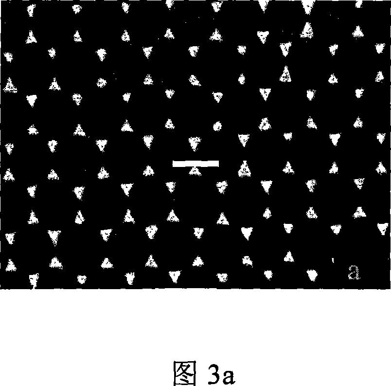
[0021] Embodiment 1 is an array-type nano-metal structure with a characteristic size of less than 70 nanometers produced by the method of the present invention.

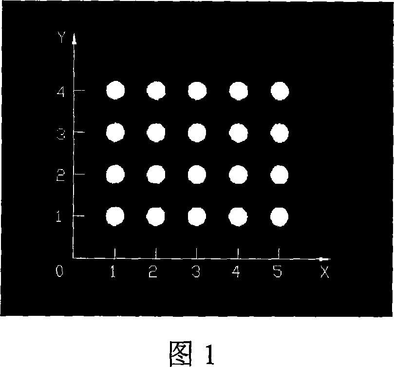
[0022] (1) Firstly, use Autocad software to design and locate the template of the micro-area, and determine the size, shape and number of arrays of the micro-area. The shape of the designed micro-area is circular, the size is 0.2mm×0.2mm, and the number of arrays is 4×5, and then the mask plate is made according to the designed positioning micro-area template data;

[0023] (2) Select a chrome-plated glass plate as the base material, and spin-coat a layer of AZ3100 resist on its surface at a speed of 6000 rpm / min for 30 seconds;

[0024] (3) Expose and develop the resist using the prepared micro-region mask; according to the depth of the resist, use an exposure amount of 10uJ / cm 2 , Shipley company developer solution MF319, concentration 100%, developing time 40-50s. Obtain the desired micro-domain structure on the...


PUM

PropertyMeasurementUnit
diameteraaaaaaaaaa
diameteraaaaaaaaaa
sizeaaaaaaaaaa

Abstract

A self-assembled packing method of photoetching-positioning includes designing array micro-region mask, using laser direct-writing mechanism to make array micro-region mast plate using coordinate value to make positioning at each micro-region, selecting Cr plated glass as substrate material and preparing a positioning micro-region template on it, self- assembling a layer of polystyrene nanoball in micro-region, depositing a layer of metal film on surface of said micro-region template, removing off self-assembled layer of polystyrene nanoball and obtaining arrayed metal nanoarray structure.

Description

technical field [0001] The invention relates to a method for manufacturing an arrayed metal nano-array structure, in particular to a photolithography positioning self-assembly filling method using a photolithography positioning technology combined with a nanosphere self-assembly technology. Background technique [0002] In recent years, with the development of micro-nano processing technology and nanomaterials, the electromagnetic properties of nano-metal structures are receiving more and more attention. The interaction between light and nano-metal structures has produced a series of new physical phenomena. When the electromagnetic wave is incident on the surface of the nano-metal array structure, the generated localized surface plasmon (LSP) will make the electromagnetic energy concentrated and enhanced violently. Based on this characteristic, localized surface plasmon LSPs have broad application prospects in energy storage, conversion, sensing and other fields. Biosensors...

Claims


Application Information

Patent Timeline
Patent Type & Authority Applications(China)
IPC IPC(8): G03F7/00G03F7/004G03F9/00
Inventor 李飞朱少丽杜春雷罗先刚
Owner INST OF OPTICS & ELECTRONICS - CHINESE ACAD OF SCI
Why Eureka
Try Eureka