Biomass pool and automatic slagoff method for the same

A technology of automatic slag discharge and biogas digester, which is applied in the direction of gas production bioreactor, waste fuel, etc. It can solve the problems of the difficulty of cleaning the crusted slag, the easy leakage of the top cover, and the difficulty of breaking, etc. Discharging, conducive to heat preservation, the effect of ensuring efficiency

Inactive Publication Date: 2007-10-17
陈观梯 +2
View PDF0 Cites 11 Cited by
  • Summary
  • Abstract
  • Description
  • Claims
  • Application Information

AI Technical Summary

Problems solved by technology

[0018] (1) Since the air pressure changes repeatedly, and generally changes between 4 and 16 kPa, the limit value of the pressure is difficult to control
It has adverse effects on the strength of the pool body and the stability and improvement of the combustion efficiency of lamps and stoves.
[0019] (2) Since there is no stirring device, the scum in the tank is easy to crust and difficult to break, so the utilization rate of the fermentation feed liquid is not high, and the gas production rate of the tank volume is low, and the general gas production rate is only 0.15...

Method used


Image

  • Biomass pool and automatic slagoff method for the same
  • Biomass pool and automatic slagoff method for the same
  • Biomass pool and automatic slagoff method for the same

Examples


Embodiment 1

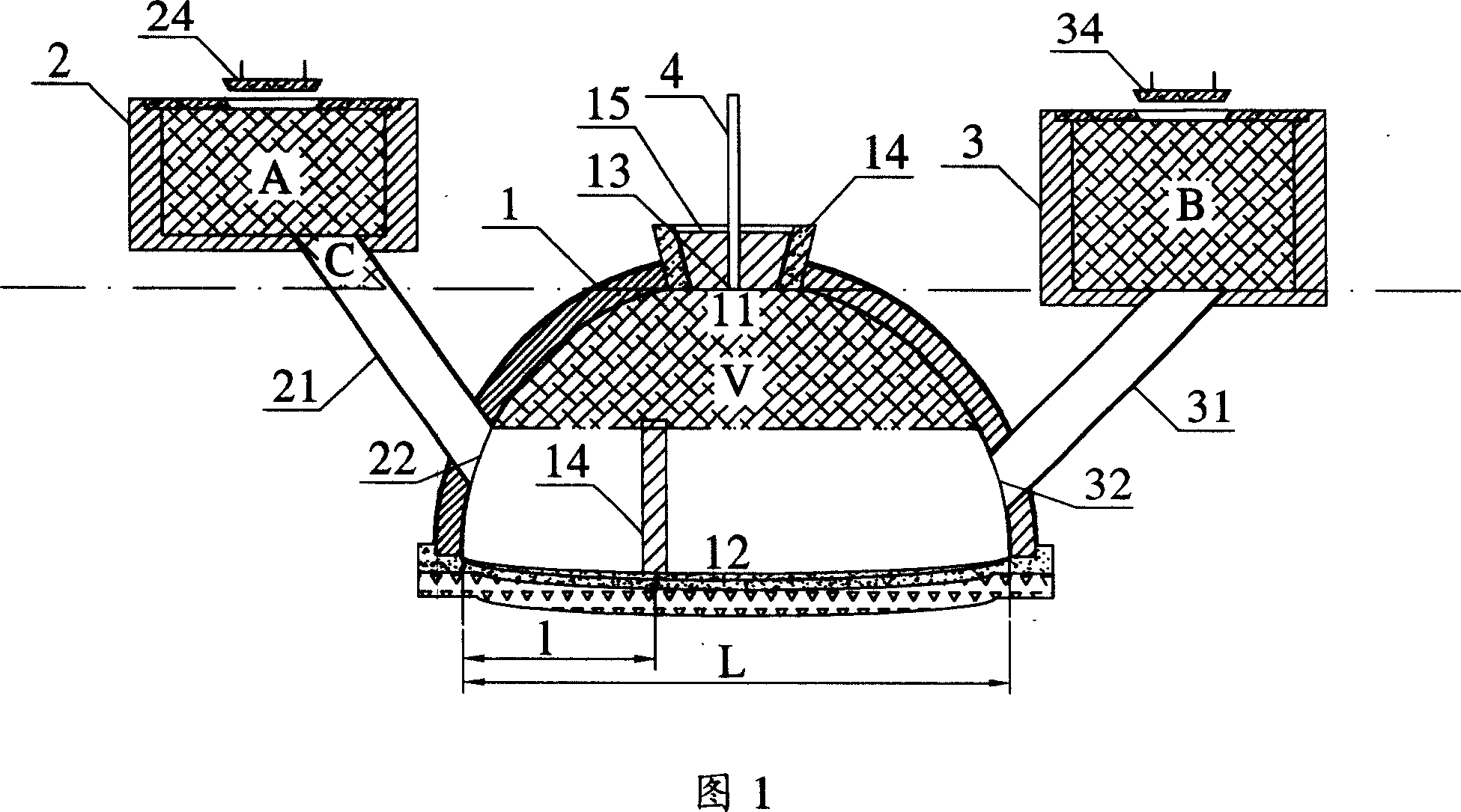
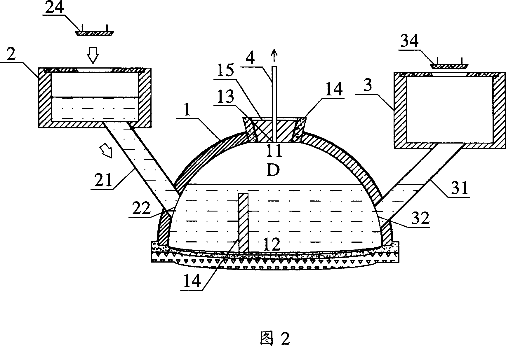
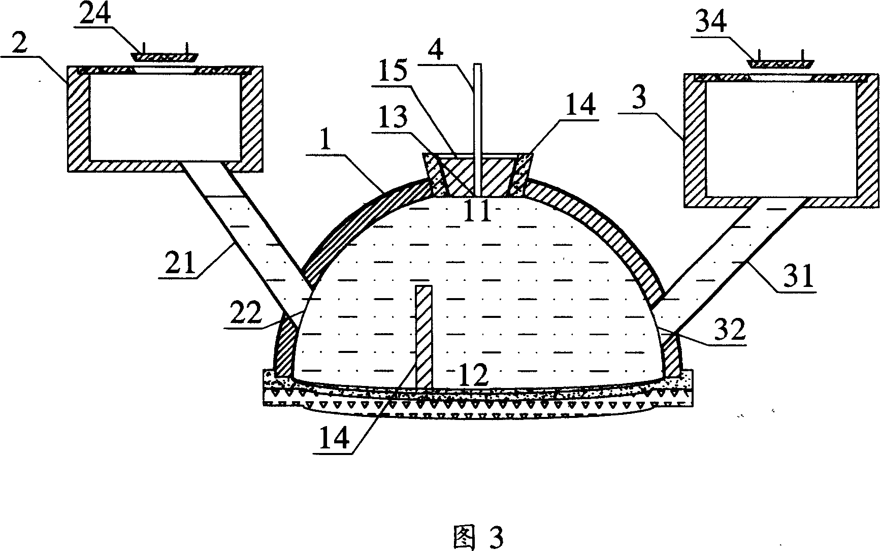
[0076] A kind of biogas digester as shown in Figure 1, comprises fermentation tank 1, feed tank 2 and discharge tank 3, feed tank 2 and discharge tank 3 are connected with fermentation tank 1 through feed pipe 21 and discharge pipe 31 respectively Connected, the fermentation tank 1 is hemispherical. In order to enable the directional flow of the fermentation feed liquid, the feed tank 2 of this embodiment is slightly higher than the discharge tank 3, the bottom of the discharge tank 3 is equal to the top 11 of the fermentation tank, and the mouth 22 of the feed pipe on the fermentation tank 1 is higher At the nozzle 32 of the discharge pipe. Under the action of hydraulic pressure, it can ensure that the fermentation feed liquid flows from the feed tank 2 to the discharge tank 3 through the fermentation tank 1 . The feed pool 2 and the discharge pool 3 are respectively provided with pool covers 21 and 31 for feeding and slag discharge. The top 11 of the fermentation tank is p...

Embodiment 2

[0083] As shown in Figure 8, the basic structure of this embodiment is the same as that of Embodiment 1, and the main structural difference is that this embodiment sets a feed port 23 and an overflow port 33 on the top side of the feed tank 2 and the discharge tank 3 respectively. , the position of the feed port 23 is slightly higher than the overflow port 33, the volume from the feed port 23 to the bottom of the pool in the feed pool 2 is A', and the volume from the overflow port 33 to the bottom of the pool in the discharge pool 3 is B' , The volume V from the upper end of the feed pipe mouth 22 to the inside of the top 11 of the fermentation tank in the fermentation tank 1 is: V=A+B+C. Also due to the problem of construction accuracy, there may be a certain error, but it should not be too large, generally controlled within 5%. The relationship between the distance l between the retaining wall 14 and the edge of the fermentation tank bottom 12 and the width L of the fermenta...

Embodiment 3

[0086]For example, there is a certain accuracy error when building a biogas digester, as shown in Figure 11. There is a certain height difference Δh between the bottom of the discharge tank 3 and the top 11 of the fermentation tank, so that in the process of feeding, when the feed liquid overflows from the bottom of the discharge tank 3, there is still a gap above the feed liquid in the fermentation tank 1. Small air chamber E. The oxygen in the air chamber E can make the upper layer of the feed liquid slagging, forming a slagging layer 52, which affects the efficiency of biogas generation. However, during the use of the present invention, the volume of the biogas chamber is constantly changing, and new feed liquid is continuously replenished, so the volume of the biogas chamber can be changed within the range of 0-V. When the dynamic air chamber is running automatically, the fermented matter in the tank is automatically floated and stirred, which can easily break the slaggin...


PUM


Abstract

The present invention relates to methane production apparatus field. The object of the present invention is to overcome the deficiency of existing technology and provides a reasonably designed, highly safe methane pool capable of removing crust of methane fluid and automatically discharging dregs and its usage method. The methane pool comprises ferment pool, feeding pool and output pool etc. The feeding pool is communicated with ferment pool through feeding tube and output tube. The feeding pool is not lower than output pool. The output pool bottom is in same level or slightly lower than ferment pool top whose feeding tube port is higher than that of output pipe. The ferment pool top is installed with gas exhaust port. The character of the present invention : (A+B+C)*1.08=V=(A+B+C)*0.92 . V represents the volume of ferment pool feeding tube port top to ferment pool top inside, A represents the volume of feeding pool, B represent the volume of output pool, C represents the feeding tube volume from ferment pool top to feeding pool bottom.

Description

technical field [0001] The invention relates to the field of biogas generating equipment, in particular to a biogas pit capable of eliminating encrustation of biogas fluid in a biogas pit and realizing automatic slag discharge without manual maintenance and an automatic slag discharge method. technical background [0002] Biogas is a combustible gas, which is produced by using organic matter such as human and animal manure under anaerobic conditions through microbial energy metabolism and respiration in a biogas digester. There are 5 people in an ordinary farm family, and 4 pigs and 1 cow are kept normally. The human and livestock feces discharged annually can produce 810-950m3 biogas per year according to theoretical calculations. After deducting the loss of manure and the pressure loss of biogas fermentation, the actual usable biogas is 500-550m3 . In the prior art, the utilization of biogas is mainly realized through a biogas digester, and the use of a biogas digester ha...

Claims


Application Information

Patent Timeline
IPC IPC(8): C12M1/107
CPCY02E50/343Y02E50/30
Inventor 朱涛
Owner 陈观梯
Why Eureka
Try Eureka