Photocatalytic sealed CO2 laser tube

A carbon dioxide and laser tube technology, applied in lasers, laser components, laser components, etc., can solve problems such as changes in working gas composition and pollution of total reflection mirrors

Inactive Publication Date: 2007-10-24
王向阳
View PDF0 Cites 22 Cited by
  • Summary
  • Abstract
  • Description
  • Claims
  • Application Information

AI Technical Summary

Problems solved by technology

[0003] In order to overcome the fact that the carbon dioxide laser tube is easily decomposed during operation, thereby changing the type and proportion of the working gas in the laser tube, the oxygen produced by the decomposition of carbon dioxide is easier to mix with the metal coaxial electrode in the laser tube and the wo

Method used


Image

  • Photocatalytic sealed CO2 laser tube
  • Photocatalytic sealed CO2 laser tube
  • Photocatalytic sealed CO2 laser tube

Examples


Embodiment Construction

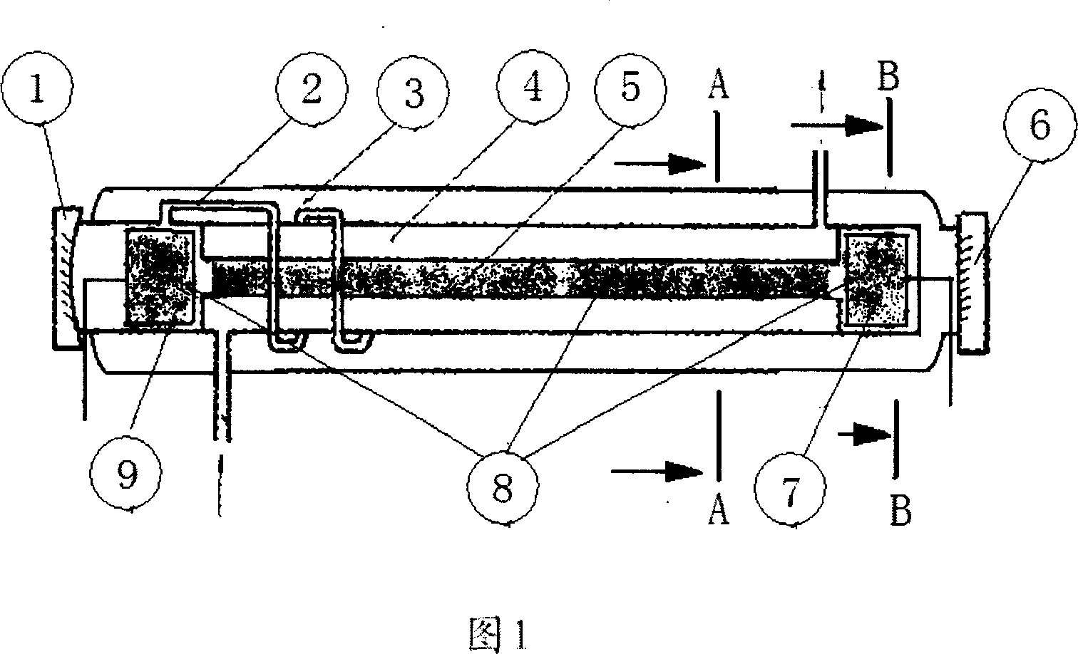
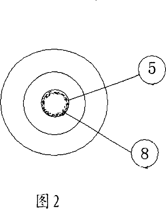
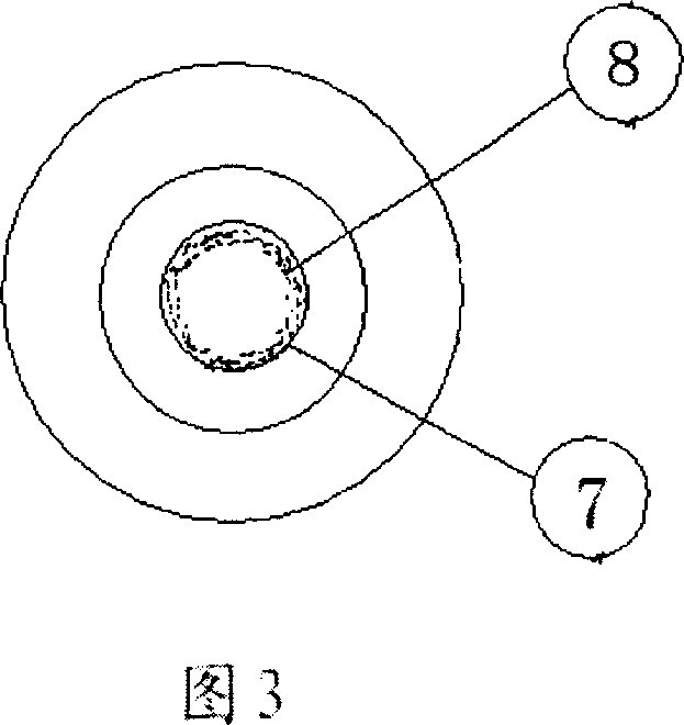
[0013] In Figure 1, the photocatalyst-enclosed carbon dioxide laser tube includes a discharge tube ⑤, a gas storage sleeve ③, a water-cooled tube ④, an output mirror ⑥, a gas return pipe ②, a gold-plated total reflection mirror ①, a cathode ⑦, and an anode ⑨. The discharge tube ⑤ and the water-cooled tube ④ are placed in the gas storage sleeve ③, the water-cooled tube ④ is set on the discharge tube ⑤, the cathode ⑦ and the anode ⑨ are placed at the two ends of the discharge tube ⑤ coaxially with the discharge tube ⑤, and the cathode ⑦ 1. The anode ⑨ is rolled into a cylindrical shape by a 0.1mm metal silver sheet, the inner wall is coated with a nano-titanium dioxide photocatalyst ⑧, and placed at both ends of the discharge tube ⑤ whose inner wall is also coated with a nano-titanium dioxide photocatalyst ⑧.

[0014] Manufacturing method:

[0015] The manufacture method of above-mentioned coated nano-titanium dioxide photocatalyst 8. is as follows: get tetra-n-butyl titanate (C...


PUM


Abstract

The related sealing-type CO2 laser tube comprises: a metal-plated full reflection mirror 1, a muffler 2 set in tube 4 to connect sheath 3 and tube 5, a gas storage sheath 3, a water cooling tube 4 set on top of a discharge tube 5 together in sheath 3, an output mirror 6 together with mirror 1 bonded on ends of laser tube ends by epoxy resin, the TiO2 photo catalyst 8 coated on inner wall of tube 5 and electrodes 7/9, and two electrodes 7/9 coaxial arranged on ends of tube 5. This invention is simple and convenient, prolongs product life time, reduces cost, and has well social and economic benefits.

Description

Technical field: [0001] The invention relates to an improved invention of a sealed-off carbon dioxide laser tube, in particular to the invention of the application of nano-titanium dioxide photocatalytic materials in the sealed-off carbon dioxide laser tube. Background technique: [0002] In the prior art, a sealed carbon dioxide laser tube is generally composed of a discharge tube, a gas storage sleeve, a water cooling tube, an output mirror, a total reflection mirror and coaxial electrodes. Among them, the discharge tube, water-cooled tube and gas storage sleeve are made of glass or quartz materials, and the total reflection mirror is generally made of glass, quartz or silicon and other materials. After polishing, the surface is coated with gold, silver and other thin films by vacuum coating method. Coaxial electrode materials are generally made of gold, silver (silver-copper alloy), tantalum, platinum, nickel, titanium and other metals or ceramic materials such as stronti...

Claims


Application Information

Patent Timeline
IPC IPC(8): H01S3/00H01S3/03H01S3/038H01S3/223
Inventor 王向阳
Owner 王向阳
Why Eureka
Try Eureka