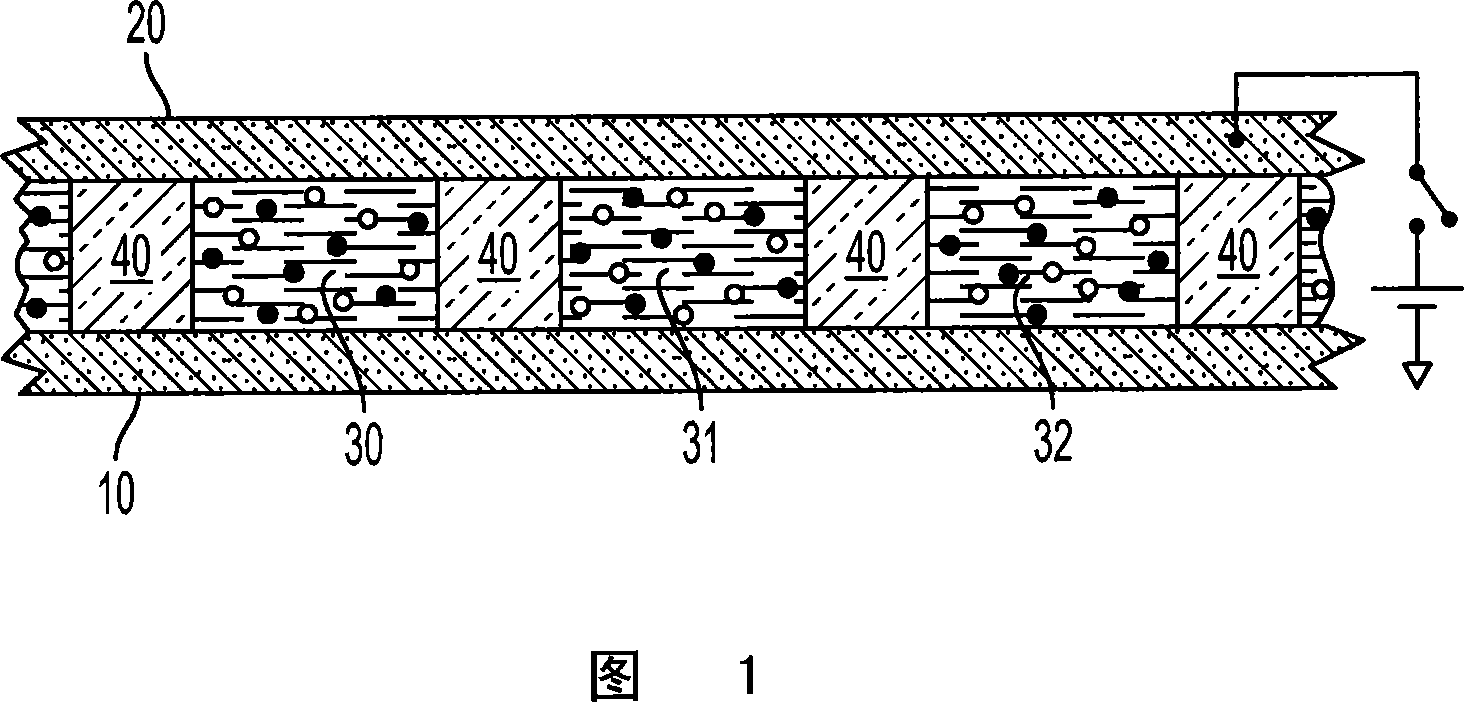
Electrophoresis display medium, component and method for using the same component to display image
A technology of electrophoretic display and display medium, which is applied in the direction of instruments, nonlinear optics, optics, etc., which can solve the problems of increased power consumption and slow switching speed of displays, and achieve the effect of fast and reliable response to electric field and low energy cost
- Summary
- Abstract
- Description
- Claims
- Application Information
AI Technical Summary
Problems solved by technology
Method used
Image

Examples
Embodiment 1
[0227] In this example, the use of emulsion aggregated particles in two particle electrophoretic displays is demonstrated.
[0228] Preparation of negatively charged emulsion aggregated cyan particles. Cyan toner particles were prepared by aggregating styrene / butyl acrylate / carboxylic acid terpolymer non-crosslinked resin particles, styrene / butyl acrylate / carboxylic acid and diethylene in the presence of two cationic coagulants. A dispersion of a second crosslinked copolymer resin of phenylbenzene and a cyan pigment to provide aggregates, which are then coalesced at a temperature above the Tg of the non-crosslinked resin to provide spherical particles. These particles were then washed (4 times) with deionized water, dried, and dry blended with an additive package comprising at least silica surface treated with polydimethylsiloxane (PDMS) and primary particle size is about 40nm. Another additive that can be used is titanic acid with alkyl functionality and a primary particle ...
Embodiment 2
[0232] In this example, the use of a silicone fluid as a fluid in a display medium with emulsion aggregated particles is demonstrated.
[0233] Two colors of emulsion aggregated toner particles were mixed with DOW 200 5 cSt fluid in a mass ratio of 1 : 1 for a solids loading of about 25%. Zirconia beads are added as a mixing aid to uniformly disperse the mixture of toner particles in the fluid. No additional external charge control agent was added.
[0234] The display medium was sandwiched between 2 parallel plates separated by 145 μm spacer spacers. A square wave voltage of + / - 200V was applied to the two plates and a color transition was observed as the two toners migrated back and forth between the two plates.
Embodiment 3
[0235] Maleic anhydride is introduced into the emulsion aggregated particles in the latex step. To bulk polymerized styrene / butyl acrylate (200ml, -20% conversion, Mn = 1,900) was added maleic anhydride (16g). The mixture was heated to ~50°C until all the maleic anhydride was dissolved. This material was added to an aqueous solution (600 g water and sodium dodecylbenzenesulfonate (SDBS) 16 g) and stirred for 5 min. The mixture obtained was piston homogenized 3 times at 500 bar and then transferred to a 1 LBUCHI reactor. The latex microemulsion was deoxygenated using argon pressurization and then decompression (5 times). The material was then heated to 135°C. After 1 hour at this temperature, ascorbic acid solution (8.5 ml at a concentration of 0.1 g / ml) was added by pump at a rate of 0.035 ml / min. The reaction was cooled after 6 hours to provide ~200 microns resin in latex at 24.9% solids, Mn = 9,700 and Mw = 23,000.
[0236] The latex is aggregated using diamines. To th...
PUM
| Property | Measurement | Unit |
|---|---|---|
| Average particle size | aaaaa | aaaaa |
Abstract
Description
Claims
Application Information
 - Generate Ideas
- Intellectual Property
- Life Sciences
- Materials
- Tech Scout
- Unparalleled Data Quality
- Higher Quality Content
- 60% Fewer Hallucinations
Browse by: Latest US Patents, China's latest patents, Technical Efficacy Thesaurus, Application Domain, Technology Topic, Popular Technical Reports.
© 2025 PatSnap. All rights reserved.Legal|Privacy policy|Modern Slavery Act Transparency Statement|Sitemap|About US| Contact US: help@patsnap.com