
Process of treating oil-containing sludge

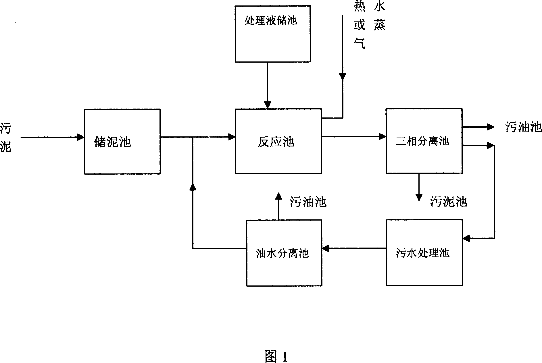
A treatment process and sludge technology, applied in sludge treatment, water/sludge/sewage treatment, sludge treatment through temperature control, etc., can solve the problems of difficult operation, low oil recovery rate, high cost, etc., and achieve Reduce environmental pollution, efficient recycling, no pollution effect

Active Publication Date: 2007-12-19
RES CENT FOR ECO ENVIRONMENTAL SCI THE CHINESE ACAD OF SCI
View PDF2 Cites 44 Cited by
  • Summary
  • Abstract
  • Description
  • Claims
  • Application Information

AI Technical Summary

Problems solved by technology

[0007] The purpose of the present invention is to overcome the existing oily sludge treatment technology or it needs to occupy a large amount of valuable land resources, there is the danger of oil and gas dissipation to pollute the atmosphere and soil seepage to pollute groundwater, or it is expensive and requires dust removal and gas washing facilities, or the operation is difficult, the conversion cycle is long, the colloid and asphaltene cannot be degraded basically, or the oil recovery rate is low, the treatment effect is poor, etc., so as to provide a non-occupancy of land resources, no pollution, low cost, Oily sludge treatment process that is simple to operate and can efficiently recover crude oil from sludge

Method used


Image

  • Process of treating oil-containing sludge

Examples


Embodiment 1

[0032] The bottom mud of a large tank of an oilfield joint station was taken, and the composition of the bottom mud is shown in Table 1. Pump the oily sludge into the sludge reaction tank, add water while stirring, add water with a water / mud weight ratio of 1.5:1 to the sludge, and then add 30000ppm of treatment solution. The composition of the treatment solution is shown in Table 2 . After completing the above process of the task, heat it up to 50°C with steam and stir it with a stirrer for 2 hours. The sludge and the mud-water mixing system of the treatment liquid are fully mixed, and the crude oil in the sludge is eluted, and then gravity separation is carried out. The separation time is 12 hours; after the above process is completed, the oil and cement are collected separately; the collected oily sewage is added with 200 mg / l polyaluminium chloride, and after 15 minutes of reaction, 2 ppm of PAM is added, and then the cyclone reactor is used for solid-liquid separation. T...

Embodiment 2

[0038] Take the bottom sludge from a large tank of an oil refinery. The composition of the bottom sludge is shown in Table 3. The ratio of water / mud was added to the sludge: 1.6:1 water and 30000ppm treatment liquid, the composition of the treatment liquid is shown in Table 4. After completing the above process of the task, put in steam to heat to 50°C and stir with a stirrer for 2 hours, then carry out gravity separation, the separation time is 12 hours; after completing the above process, collect oil and cement separately; add 200mg of oily sewage to the / l of polyferric sulfate, add 2ppm of PAM after 15 minutes of reaction, and then use a gravity settling tank for solid-liquid separation. The hydraulic retention time of the reactor is 2 minutes, and the treated sewage is reused. The sludge and Dirty oil is collected separately. The concentration of crude oil in the treated sludge is less than 0.5wt%.

[0039] Table 3. Composition of tank bottom mud

[0040] samp...


PUM


Abstract

The present invention relates to oil-containing sludge treating process, which includes the following steps: pumping oil-containing sludge into sewage reacting tank and adding water while stirring; adding treating solution; heating and stirring to separate oil from sludge; adding coagulant while stirring to react for 2-30 min, adding polyacrylamide, stirring and solid-liquid separating into three layers; collecting oil, water and sludge separately; and collecting the sludge with oil content less than 1 wt% in the sludge collecting tank and further solidification or draining. The present invention has the advantages of recovering oil, reducing environmental pollution, low cost, etc.

Description

technical field [0001] The invention belongs to the field of wastewater treatment, and in particular relates to a treatment process for oily sludge. Background technique [0002] A large amount of sludge will be generated in the process of oil drilling, development, storage and transportation, and oil refining. When oil storage tanks store oil, especially crude oil, during the long-term storage process, a small amount of mechanical impurities in the oil, Sand, soil, heavy metal salts, and heavy oily components such as paraffin and asphaltene naturally settle and accumulate at the bottom of the oil tank due to poor specific gravity, forming a black and thick gelatinous layer. When the tank is cleaned, it must be cleared out of the tank, resulting in oil tank bottom sludge, the amount of which is generally more than 1% of the storage tank capacity, and it has also been reported as 2.2%. [0003] The composition of oil tank bottom sludge is very complex and cannot be discharge...

Claims


Application Information

Patent Timeline
Patent Type & Authority Applications(China)
IPC IPC(8): C02F11/00C02F11/18C02F11/14
Inventor 杨敏王振宇高迎新丁然张昱
Owner RES CENT FOR ECO ENVIRONMENTAL SCI THE CHINESE ACAD OF SCI
Learn More