Oxygen sensor and air/fuel ratio control system

一种氧传感器、控制系统的技术,应用在燃料喷射控制、电气控制、发动机控制等方向,能够解决空燃比控制精度下降、误差、影响控制的参数等问题,达到提高输出精度的效果

Inactive Publication Date: 2007-12-19
TOYOTA JIDOSHA KK
View PDF2 Cites 5 Cited by
  • Summary
  • Abstract
  • Description
  • Claims
  • Application Information

AI Technical Summary

Problems solved by technology

[0003] However, in the output of the air-fuel ratio sensor, errors occur due to variations in the output characteristics of the air-fuel ratio sensor and changes in output characteristics over time.
If the control parameters are calculated only based on the output of the air-fuel ratio sensor on the upstream side, when the output of the air-fuel ratio sensor produces an error, the error will directly affect the control parameters
As a result, the accuracy of air-fuel ratio control decreases

Method used


Image

  • Oxygen sensor and air/fuel ratio control system
  • Oxygen sensor and air/fuel ratio control system
  • Oxygen sensor and air/fuel ratio control system

Examples


Embodiment approach 1

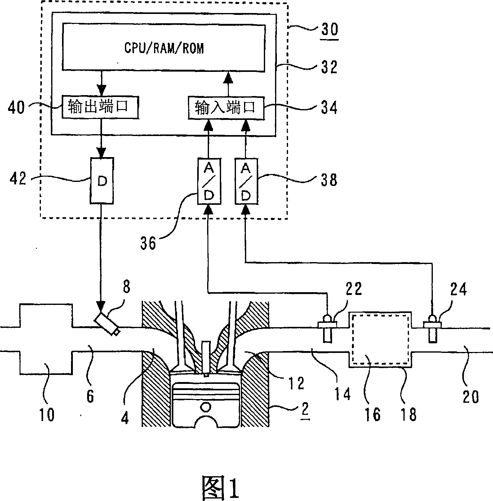
[0122] FIG. 1 is a schematic diagram for explaining a system according to Embodiment 1 of the present invention.

[0123] As shown in FIG. 1 , the system of Embodiment 1 includes an internal combustion engine 2 . An intake branch pipe 6 is connected to the intake port 4 of each cylinder of the internal combustion engine 2 . A fuel injection valve 8 is provided on the intake branch pipe 6 . Also, the intake branch pipe 6 is connected to a common buffer tank 10 .

[0124] On the other hand, the exhaust ports 12 of the respective cylinders of the internal combustion engine 2 are connected to a common exhaust manifold 14 . The exhaust manifold 14 is connected to a catalytic converter 18 with a built-in three-way catalyst 16 . The catalytic converter 18 is connected to a muffler (not shown) through an exhaust pipe 20 . The upstream side sensor 22 is arranged on the exhaust manifold 14 , that is, upstream of the three-way catalyst 16 . The upstream sensor 22 is a so-called glob...

Embodiment approach 2

[0153] The configuration of the system used in Embodiment 2 is the same as that of the system described in Embodiment 1. However, the control device 30 is based on the output V of the downstream side sensor 24 24 The target voltage at the time of deviation is calculated, and two target voltages Vref1 and Vref2 are stored. FIG. 4 is a graph for explaining the relationship between the output of the downstream sensor 24 and the two target voltages Vref1 and Vref2 in the second embodiment of the present invention.

[0154] As shown in FIG. 4 , in the downstream side sensor 24, in a low-concentration atmosphere, the output characteristic of the air-fuel ratio when the air-fuel ratio is changed from rich to lean is hysteresis. That is, the output of the downstream side sensor 24 differs when the air-fuel ratio changes from rich to lean and when the air-fuel ratio changes from lean to rich. Specifically, when the air-fuel ratio is switched from rich to lean, the output abrupt chang...


PUM

PropertyMeasurementUnit
porosityaaaaaaaaaa
porosityaaaaaaaaaa

Abstract

In the oxygen sensor, the correct output can also be obtained for the low-concentration exhaust gas downstream of the three-way catalyst. The reference gas side electrode of the reference gas as the oxygen concentration reference; the electrolyte disposed between the exhaust side electrode and the reference gas side electrode, further, has a lowering unit on the surface side of the exhaust side electrode, so that the lead-in exhaust side electrode The amount of exhaust gas flowing to the outside of the oxygen sensor is relative to the amount of exhaust gas flowing to the outside of the oxygen sensor, and the amount of exhaust gas that is less than that introduced into the electrode of the air-fuel ratio sensor is relative to the amount of exhaust gas flowing to the outside of the air-fuel ratio sensor.

Description

technical field [0001] The invention relates to an oxygen sensor and an air-fuel ratio control system. Specifically, it relates to an oxygen sensor arranged downstream of a catalyst of an internal combustion engine, and sensors provided upstream and downstream of the catalyst of the internal combustion engine, respectively, and the output of the oxygen sensor on the downstream side is used to correct the output of the air-fuel ratio sensor on the upstream side, and control Air-fuel ratio control system for air-fuel ratio. Background technique [0002] Japanese Patent Laid-Open No. 10-306742 discloses a system in which an air-fuel ratio sensor is arranged upstream of a three-way catalyst provided in an exhaust passage of an internal combustion engine. The system calculates the control parameter of the air-fuel ratio according to the output of the air-fuel ratio sensor, and controls the air-fuel ratio to be the target air-fuel ratio through the parameter. [0003] However, i...

Claims


Application Information

Patent Timeline
Patent Type & Authority Applications(China)
IPC IPC(8): G01N27/409F02D41/14F02D45/00
CPCF02D41/1454G01N27/4077
Inventor 青木圭一郎
Owner TOYOTA JIDOSHA KK
Why Eureka
Try Eureka