
Soldering joint automatic tracking control method based on alternating field measuring technique and equipment thereof

A technology of alternating magnetic field and measurement technology, used in welding equipment, arc welding equipment, metal processing equipment, etc., can solve the problems of narrow application range, low control accuracy, low manufacturing cost, etc., to achieve stable and reliable operation, tracking The effect of high precision and improved accuracy

Inactive Publication Date: 2008-01-23
XIANGTAN UNIV
View PDF0 Cites 19 Cited by
  • Summary
  • Abstract
  • Description
  • Claims
  • Application Information

AI Technical Summary

Problems solved by technology

At present, the weld seam tracking sensors commonly used are mechanical arc sensors and laser sensors. In the weld seam tracking control system using mechanical arc sensors, the arc itself is used as the sensor, which has strong real-time performance and good flexibility and reliability of welding torch movement. , the manufacturing cost is low, but the control accuracy is not too high, the volume is large, the noise is large, and it is easy to wear
Although the control accuracy of the laser sensor is relatively high, its cost is high and the scope of application is narrow. In some occasions, even laser tracking is difficult to meet the requirements.
In recent years, alternating magnetic field measurement technology (abbreviated as ACFM technology) has been developed and applied, such as "Research and Development of ACFMS Control System" Military Automation-1996 Issue 4, "Application of ACFM Method on Tracks and Vehicles "Foreign Locomotive and Rolling Stock Technology - 2006 Issue 2, "ACFM Detection System Electromagnetic Compatibility Reliability Prediction", Petroleum Industry Technical Supervision - 2005 10 Issue, "Orthogonal Signal Source Design Used in ACFM Nondestructive Testing Instruments" Electronic Design Application - 2004, No. 11, "Defect Recognition Model of Alternating Magnetic Field Measurement", Nondestructive Testing - 2005, No. 3, "Mathematical Model of Alternating Magnetic Field Measurement and Establishment of Quasi-uniform Field", Nondestructive Testing - 2004, No. 11, "Alternating Magnetic Field Numerical Simulation Analysis of Measurement System "Instrument Technology and Sensors-2003 6th Issue, "Design of Magnetic Sensor in Alternating Magnetic Field Measurement System" Sensor World-2003 12th Issue, "Metal Surface Defect Detection Using Alternating Magnetic Field Measurement Method" Bing Industrial Automation - Issue 2, 2004, "Nondestructive Testing Alternating Magnetic Field Measurement Method" Nondestructive Testing - Issue 3, 2001, through search and analysis, it can be known that the sensor based on alternating magnetic field measurement technology (ACFM) has the advantages of simple device, high control precision, and no need for It has the characteristics of contact with the weldment, no need for calibration, fast detection speed and good adaptability. At present, it is mainly used in defect detection. Related reports on the application of variable magnetic field measurement technology in automatic seam tracking

Method used


Image

  • Soldering joint automatic tracking control method based on alternating field measuring technique and equipment thereof
  • Soldering joint automatic tracking control method based on alternating field measuring technique and equipment thereof
  • Soldering joint automatic tracking control method based on alternating field measuring technique and equipment thereof

Examples


Embodiment 1

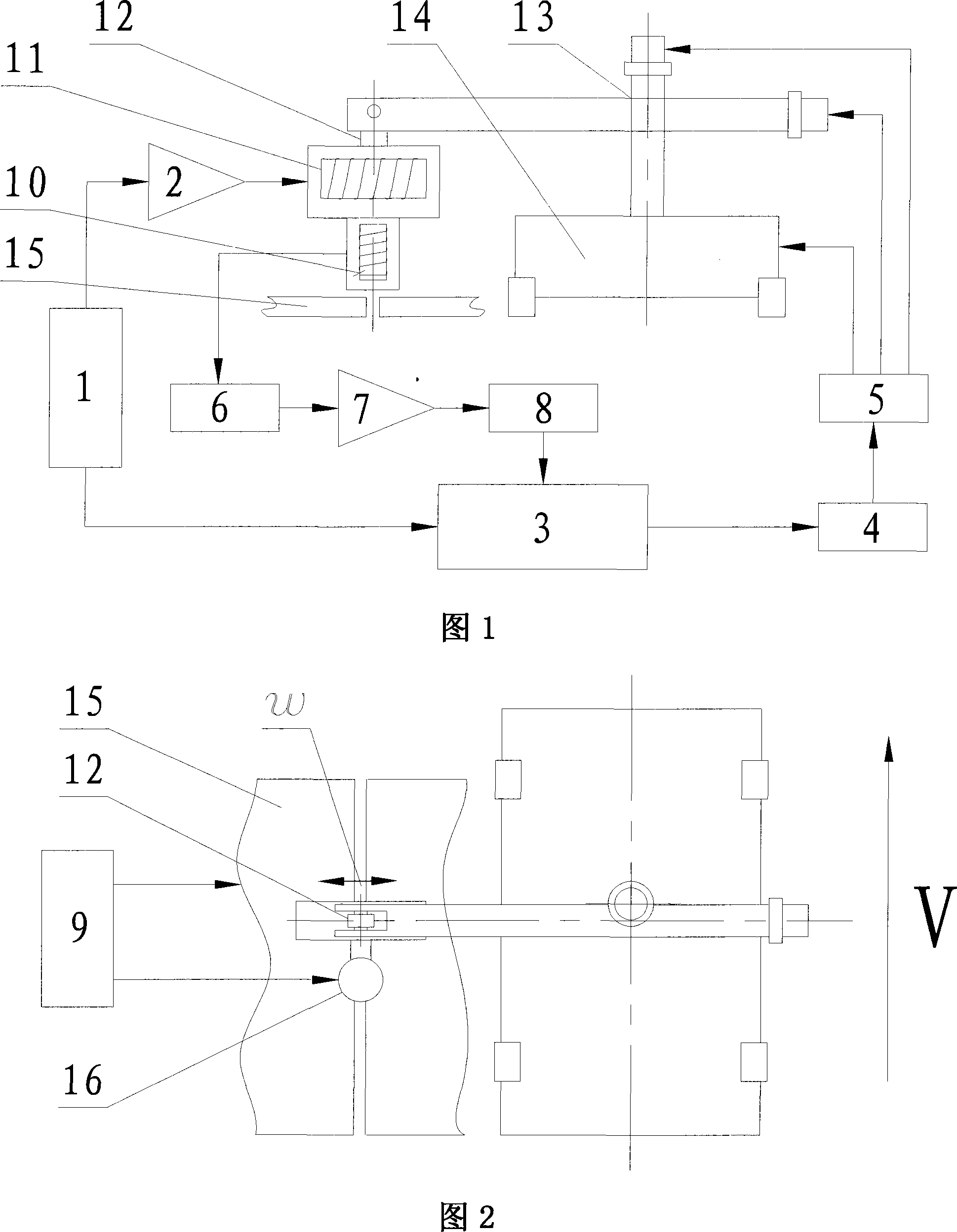
[0015] Embodiment 1, the whole structure of the present invention comprises the welding part that is made up of welding torch 16, welding power source 9 and the tracking control part that is made up of welding seam tracking sensor etc. based on alternating magnetic field measurement technology; Sensor and welding torch 16 are installed in tracking control Part of the cross slider 13. The tracking control part is composed of a seam tracking sensor based on alternating magnetic field measurement technology, an excitation signal source 1, a swing device 12, a computer controller 3, a drive controller 5, an actuator and various peripheral functional circuits.

[0016] The seam tracking sensor based on the alternating magnetic field measurement technology consists of an excitation coil 11 and an induction coil 10 . The excitation signal source 1 generates a sine wave signal in a certain frequency range, and through the power amplifier circuit 2, the excitation coil 11 is driven to ...


PUM


Abstract

A welding line automatic tracking control method and equipment based on alteration magnetic field measuring technology are provided, which is used for solving the technology problem of the existing I-shape divided edge welding line with difficult tracking and low accuracy. The invention is composed of a welding component and a tracking control component, the tracking control system is composed of a welding tracking sensor, an activating signal resource, a swing device, a computer controller, a drive controller, an implement structure and each surrounding function circuit based on alternate magnetic measuring technology; the swing device drives the welding line tracking sensor to proceed scanning to the welding line divided edge, after processing by a signal process circuit, an operation enlarge circuit and a A / D converse circuit, the scanned welding line divided edge are transferred into the compute controller and then output into a D / A conversing circuit after the second time process, the D / A transferring circuit is processed and then send to the drive controller, thus controlling the motor movement of a welding wheelbarrow and a cross sliding block, which makes the welding gun proceed automatic tracking welding line to finish automatic welding. The invention has the characters of simple structure, quick testing, high tracking accuracy and good reliability, which can be widely used I shape divided edge welding line automatic tracking system.

Description

technical field [0001] The invention relates to a welding control method, in particular to a control method and equipment for automatic welding. Background technique [0002] The main problem to be solved in realizing the automatic control of the welding process is the automatic tracking of the welding seam. At present, the weld seam tracking sensors commonly used are mechanical arc sensors and laser sensors. In the weld seam tracking control system using mechanical arc sensors, the arc itself is used as the sensor, which has strong real-time performance and good flexibility and reliability of welding torch movement. , The manufacturing cost is low, but the control accuracy is not too high, the volume is large, the noise is large, and it is easy to wear. Although the control accuracy of the laser sensor is relatively high, its cost is high and its application range is narrow. In some occasions, even laser tracking is difficult to meet the requirements. In recent years, alt...

Claims


Application Information

Patent Timeline
IPC IPC(8): B23K9/127
Inventor 洪波李安强尹力屈岳波
Owner XIANGTAN UNIV
Learn More