A manufacturing method of flange type linear bushing by laser and linear bushing manufactured by the above method
A flange and linear technology, applied in the direction of manufacturing tools, laser welding equipment, workpiece edge, etc., can solve the problems of difficult automatic processing, dimensional deviation, and reduce the metal strength of the base material, so as to reduce production costs, strengthen welding parts, The effect of good welding performance
- Summary
- Abstract
- Description
- Claims
- Application Information
AI Technical Summary
Problems solved by technology
Method used
Image
Examples
no. 1 approach
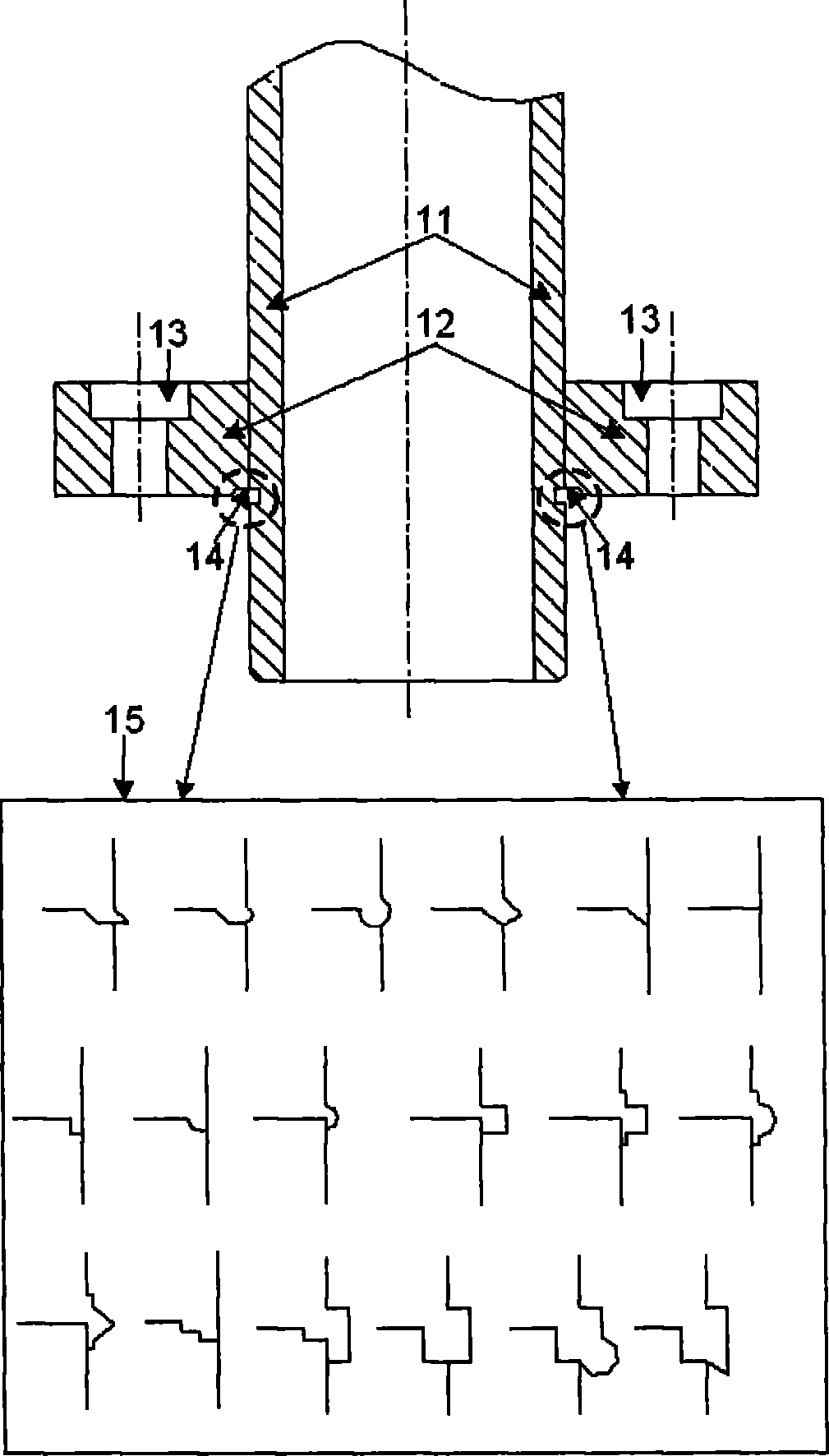
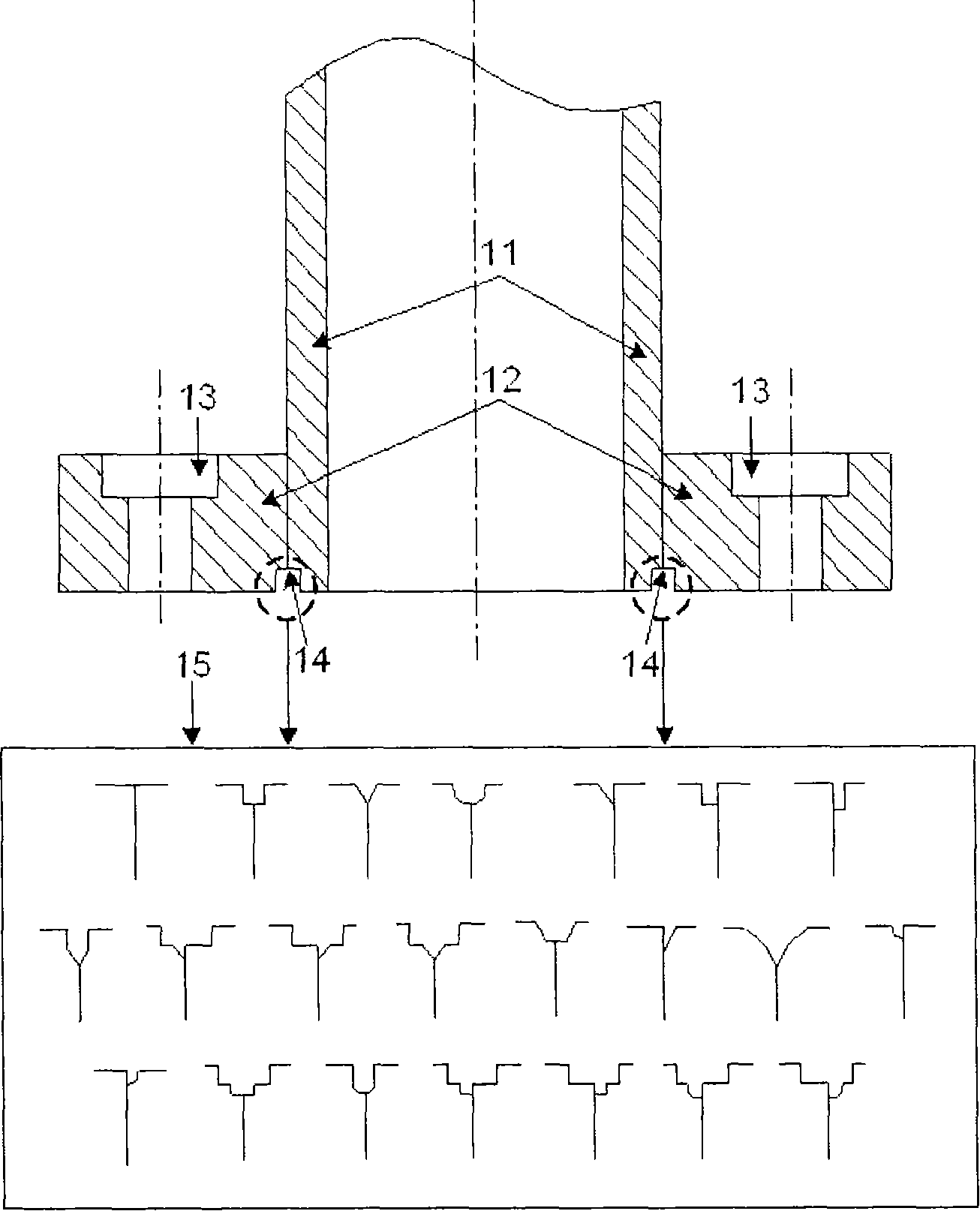
[0040] The first preferred embodiment of the present invention relates to a method for manufacturing a flanged linear bushing by processing the inner edge of the flange and using a high-energy beam with better linearity. The method for manufacturing a flanged linear bushing includes the following steps: a) processing the inner edge of the flange to be connected with the outer sleeve along the inner circumference of the flange for easy connection and better welding, It is also convenient to eliminate the interference between the protruding melting and welding surface of the flanged linear bushing and the reference plane of the application base when the application base is installed; b) at the right angle between the flange plane and the axis of the outer casing, Mechanically connect the outer sleeve and the processed flange; and c) use a high-energy beam with good linearity to weld the inner edge of the processed flange and the connection part of the outer sleeve.
no. 2 approach
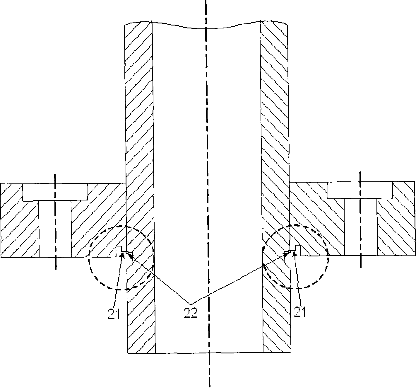
[0042] The second preferred embodiment of the present invention relates to a method for manufacturing a flanged linear bushing, which includes forming different structures so that the outer sleeve and the flange are easily mechanically connected and welded to each other; and after precise connection The step of welding the connection part using a high energy beam. Specifically, the method of manufacturing a flanged linear bushing includes the following steps: a) processing the edge of the outer sleeve at a predetermined angle, so that the outer sleeve and the flange are smoothly connected mechanically; b) considering the outer sleeve The thickness of the outer sleeve is to form a recess of predetermined depth and width on the outer surface of the outer sleeve to allow the high-energy beam (laser or electron beam) with good linearity to easily enter, and to allow the flange to be connected to the outer sleeve. C) machining the inner edge of the flange along the inner circumferen...
no. 3 approach
[0045] The third preferred embodiment of the present invention relates to a method of manufacturing a flanged linear bushing using filler metal to prevent defects in the welded part and provide high-quality welding of the connecting part, because the filler metal and the connecting part The materials melt together and penetrate into the welded part between the flange and the outer sleeve. The filler metal can absorb the stress generated by the high energy of the welding. The flange and the outer sleeve are made of materials with different compositions. to make.
[0046] The method of manufacturing the flanged linear bushing using filler metal will be described in more detail. After step b) of the first embodiment, the method of manufacturing a flanged linear bushing using filler metal in the first preferred embodiment further includes the following steps: c) placing filler metal made of alloy and having a predetermined diameter in The position between the flange and the outer sl...
PUM
 Abstract
Description
Claims
Application Information
 - R&D
- Intellectual Property
- Life Sciences
- Materials
- Tech Scout
- Unparalleled Data Quality
- Higher Quality Content
- 60% Fewer Hallucinations
Browse by: Latest US Patents, China's latest patents, Technical Efficacy Thesaurus, Application Domain, Technology Topic, Popular Technical Reports.
© 2025 PatSnap. All rights reserved.Legal|Privacy policy|Modern Slavery Act Transparency Statement|Sitemap|About US| Contact US: help@patsnap.com


