Silicon MEMS piezoresistance type acceleration sensor

An acceleration sensor, piezoresistive technology, applied in the field of micromechanical sensors, can solve the problems of reducing sensor accuracy and increasing processing difficulty, achieving the effects of light weight, easy three-axis integration, and reduced processing difficulty

Active Publication Date: 2008-02-06
THE 13TH RES INST OF CHINA ELECTRONICS TECH GRP CORP
View PDF0 Cites 30 Cited by
  • Summary
  • Abstract
  • Description
  • Claims
  • Application Information

AI Technical Summary

Problems solved by technology

Making the piezoresistor on the side of the cantilever can measure the acceleration signal in the horizontal direction, but it must be re

Method used


Image

  • Silicon MEMS piezoresistance type acceleration sensor
  • Silicon MEMS piezoresistance type acceleration sensor

Examples


Example Embodiment

[0016] Example 1

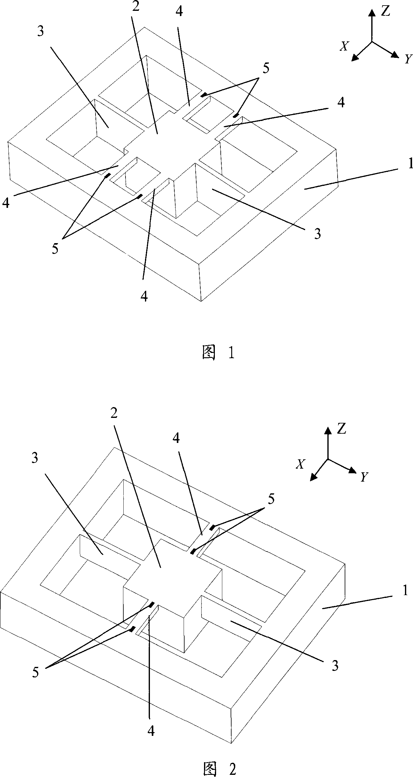
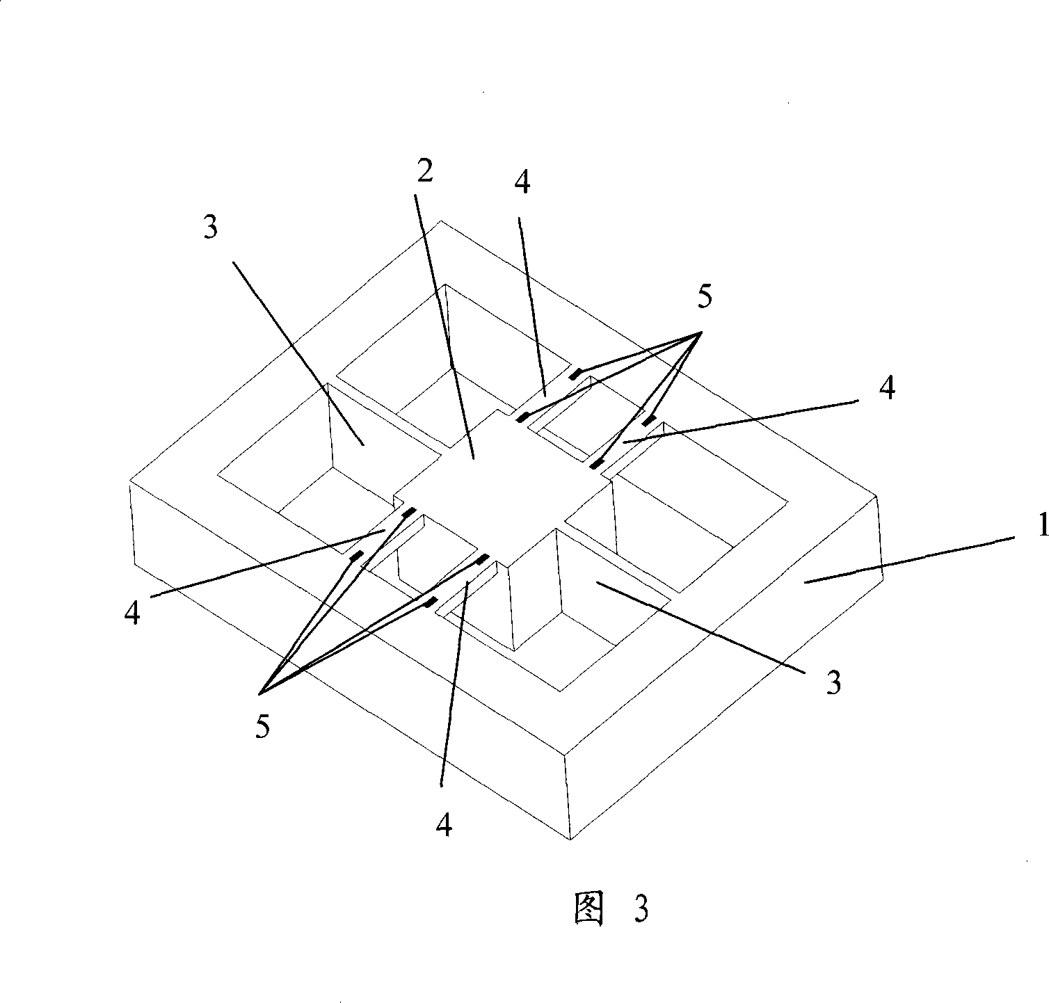
[0017] As shown in Figure 1. The silicon MEMS piezoresistive acceleration sensor of the present embodiment is to arrange a quality block 2, two torsion beams 3 and four sensitive beams 4 in a silicon frame 1, and the mass block 2 is positioned at the middle of the silicon frame 1, and passes through the torsion beam 3. The sensitive beam 4 is connected to the silicon frame 1; the sensitive beam 4 is symmetrically distributed on the left and right sides of the mass block 2, and the torsion beam 3 is located on the front and rear sides of the mass block 2; the height of the sensitive beam 4 in the vertical direction and the width in the horizontal direction Far smaller than the height and width of the mass block 2; the torsion beam 3 is located on the centerline of the planes on both sides of the mass block 2, the height of the torsion beam 3 in the up and down direction is the same as that of the mass block 2, and the width in the horizontal direction is smal...

Example Embodiment

[0018] Example 2

[0019] as shown in picture 2. The difference between this embodiment and Embodiment 1 is that there is one sensitive beam 4 on the left and right sides of the mass block 2, and the two sensitive beams 4 are symmetrically distributed on the center line of the left and right planes of the mass block 2. A piezoresistor 5 is arranged at both ends of the beam 4 respectively, and four piezoresistors can form a measuring bridge. A pair of torsion beams 3 are arranged on the front-to-back centerline of the mass block, the vertical height of which is greater than the vertical height of the sensitive beam 4 and smaller than the vertical height of the mass block 2 .

Example Embodiment

[0020] Example 3

[0021] The difference between this embodiment and Embodiment 1 is that a piezoresistor 4 is respectively arranged at both ends of each sensitive beam 4, and there are 8 piezoresistors on the four sensitive beams, which can form two measurement circuits. bridge.


PUM


Abstract

The present invention discloses a silicon MEMS piezoresistive acceleration sensor which belongs to the art of micro-mechanical sensors. The present invention comprises a silicon frame, a quality block, a torsion girder, a sensitive girder and a voltage dependent resistor; wherein, the left and the right sides of the quality block are provided with sensitive girders in symmetry which are connected with the silicon frame, and the end part on the upper surface of the sensitive girder is provided with the voltage dependent resistor; the front and the rear sides of the quality block are provided with a pair of symmetrical torsion girders which are connected with the silicon frame, the height of the quality block is vertically higher than that of the sensitive girder. The piezoresistive acceleration sensor provided by the present invention is a micro sensor using the voltage dependent resistor that is arranged on the upper surface of the structure to test the lateral acceleration signal; can avoid the sophisticated technique making the voltage dependent resistor on the profile of the structure; reduces the difficulty of processing; improves the accuracy, consistency and good yield of resistor processing; and easily realizes three-axial integration. The sensor has the advantages of small body, light weight, small crossover coupling, high reliability, low cost and easy combination.

Description

technical field [0001] The invention relates to an acceleration sensor made by adopting the piezoresistive principle, which belongs to the field of micromechanical sensors. Background technique [0002] The micro-acceleration sensor is a sensor made by micro-machining technology. According to different working principles, micro-acceleration sensors can be divided into capacitive, piezoresistive, heat flow, tunneling and resonance. Compared with other forms of micro-acceleration sensors, piezoresistive micro-acceleration sensors have been widely used because of their simple processing technology, convenient testing and low cost. The piezoresistive acceleration sensor is based on the piezoresistive effect of semiconductors and consists of a mass block and a cantilever beam. The manufacture of piezoresistors is the key technology to realize MEMS piezoresistive acceleration sensors. The current processing technology is mainly to manufacture piezoresistors on the upper surface ...

Claims


Application Information

Patent Timeline
IPC IPC(8): G01P15/12B81B7/02
Inventor 杨拥军徐淑静吕树海
Owner THE 13TH RES INST OF CHINA ELECTRONICS TECH GRP CORP
Why Eureka
Try Eureka