
Low temperature plasma device for treating volatile organic

A technology of low-temperature plasma and volatile organic compounds, applied in the direction of plasma, chemical/physical/physicochemical processes of energy application, separation methods, etc., can solve problems such as breakdown, affecting processing efficiency, easy to form arcs, etc., and achieve gas The effect of improving discharge, improving processing efficiency, and improving utilization rate

Inactive Publication Date: 2008-02-13
BEIJING UNIV OF TECH
View PDF2 Cites 12 Cited by
  • Summary
  • Abstract
  • Description
  • Claims
  • Application Information

AI Technical Summary

Problems solved by technology

For example, patent 02209303.6 discloses a plasma waste gas purification device. The top of the ionization chamber is equipped with an ion gun that can move up and down. The air inlet and the gas outlet are respectively located on both sides of the ionization chamber. It is limited, and the effective utilization rate of the plasma is low, so some gases cannot or are not completely degraded, which affects its processing efficiency
Patent 200420150218.7 discloses a needle-plate pulse discharge plasma-induced photocatalytic treatment device for organic wastewater, which can also be used to treat organic waste gas. This device uses a needle-plate electrode structure, and the needle-shaped discharge electrodes are solid or hollow Yes, the hollow discharge electrode is an ordinary metal tube, which is not conducive to gas discharge and air jet injection, and affects the effective use of plasma; the low-voltage electrode in the device is a grounded metal plate, and there is no dielectric barrier between the high-voltage electrode and the device. The arc is formed, which leads to breakdown, affects the normal operation of the equipment, and makes the processing efficiency unguaranteed

Method used


Image

  • Low temperature plasma device for treating volatile organic
  • Low temperature plasma device for treating volatile organic
  • Low temperature plasma device for treating volatile organic

Examples


Embodiment Construction

[0024] This embodiment will be described in detail below with reference to FIGS. 1 to 5 .

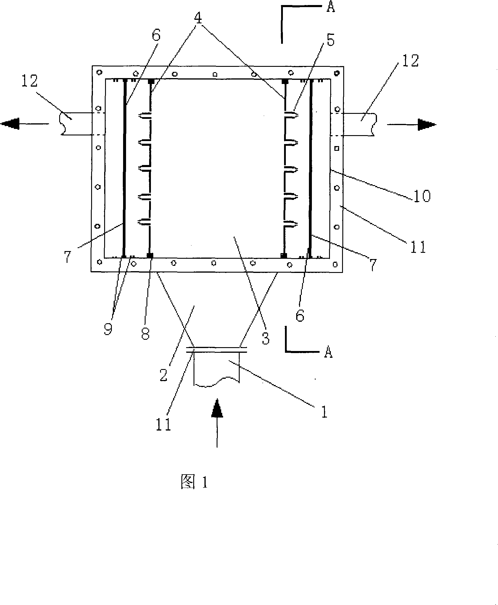
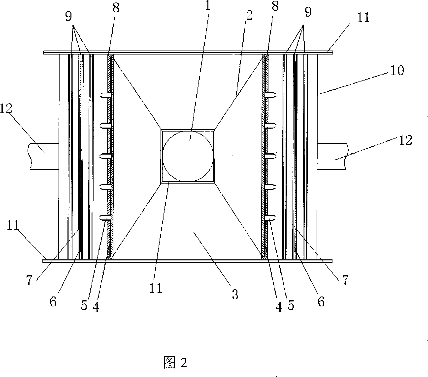
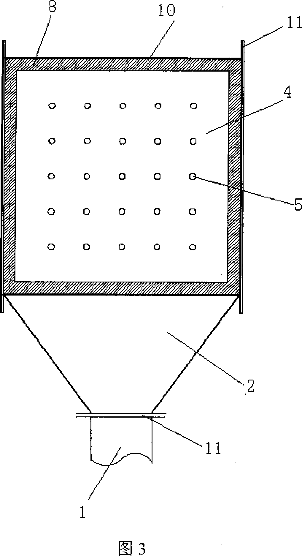
[0025] As shown in Figure 1 and Figure 2, this embodiment mainly includes an air inlet 1, a diffuser 2, and a reactor shell 10, the air inlet 1 is connected to the diffuser 2 through a flange 11, and the diffuser 2 It is fixedly connected with the reactor shell 10. The reactor shell 10 is a cuboid structure, and its internal structure is symmetrically distributed. Insulation slots 8 and 9 are provided on the upper and lower sides of the reactor shell 10. The high-voltage pole plate 4 connects with the reactor shell through the insulation slot 8 The body 10 is connected, the dielectric barrier layer 6 is close to the grounding plate 7 and fixed by the slot 9, and there is a gap of 15 mm between the front and rear sides of the grounding plate 7 and the dielectric barrier layer 6 and the reactor shell 10. Pass through the treated exhaust gas. The space enclosed by the two high-pressure p...


PUM


Abstract

The present invention relates to a low temperature plasma device for disposing volatile organic matter and belongs to the volatile organic exhaust gas disposal field. An air inlet (1) of the device is connected with a reactor crust (10) by a gradually diffusing apparatus (2). A high pressure polar plate (4) is arranged inside the reactor crust (10), and the high pressure polar plate (4) is connected with the reactor crust (10). The high pressure pole nozzles (5) are uniformly distributed on the high pressure polar plate (4) and are used for producing the plasmas. A ground plate (7) is arranged between the high pressure polar plate (4) and the reactor crust (10). A gap is left between the ground plate (7) and the reactor crust (10) for air to pass. The air outlets (12) are arranged at two side faces of the reactor crust (10). The present invention improves the utilization rate of the plasma, and a medium baffle layer avoids occurrence of electric arc. The present invention also has the advantages of simple structure, strong applicability, high disposal efficiency and low operation charge.

Description

technical field [0001] The invention relates to a low-temperature plasma device for processing volatile organic compounds, which belongs to the field of processing volatile organic compounds. Background technique [0002] Volatile organic compounds (VOCs for short) are a large class of important air pollutants, which refer to organic compounds whose saturated vapor pressure exceeds 70.91Pa at normal temperature and boiling point at normal pressure is less than 260°C, and their main components are hydrocarbons. , oxygen hydrocarbons, halogenated hydrocarbons, nitrogen hydrocarbons and sulfur hydrocarbons, etc. The hazards of VOCs mainly include the following aspects: (1) Most VOCs are odorous and toxic. Many substances in VOCs are carcinogenic, teratogenic, and mutagenic. (2) Under the irradiation of light, many VOCs can easily undergo photochemical reactions with some oxidants to generate photochemical smog, which is harmful to human health and affects the growth of crops; ...

Claims


Application Information

Patent Timeline
IPC IPC(8): B01D53/76B01D53/72B01J19/08H05H1/32H05H1/34
Inventor 李坚豆宝娟梁文俊竹涛金毓峑
Owner BEIJING UNIV OF TECH
Learn More