Polymer self-lubricating thin layer composite axle sleeve and its preparation method

A composite shaft sleeve, polymer technology, applied in the direction of bearing components, shafts and bearings, mechanical equipment, etc., can solve the problems of poor wear resistance, easy occlusal pair friction, poor bonding strength, etc., to improve the bearing capacity and wear resistance. Long life, good water corrosion resistance, and the effect of improving load-carrying capacity

Active Publication Date: 2008-02-20
COB PRECISION PARTS
View PDF1 Cites 33 Cited by
  • Summary
  • Abstract
  • Description
  • Claims
  • Application Information

AI Technical Summary

Problems solved by technology

However, in order to meet the design requirements of modern automobile structures, the moving friction pairs in automobile door hinges, pedals, joysticks and automatic door and window systems need to have a large installation gap, and the lubricating materials need to have good flexibility and thinner Wall thickness to avoid deformation of the material due to creep, which is an obvious weakness for conventional multilayer composites sintered on the surface of metal-based substrates
[0003] The Chinese invention patent (publication number CN1292852A, patent name "sliding bearing") proposed by Dana Corporation of the United States sinters spherical copper alloy powder on a copper-clad steel plate at a certain temperature, and the surface is sintered with polytetrafluoroethylene (PTFE) as The polymer material of the main resin is used to manufacture bearings through the rolling process. This type of lubricating material has a high load-carrying capacity, but because the surface self-lubricating modified layer is very thin, only 0.03-0.05mm, and the wall thickness of the formed bearing can only be Above 0.75mm, the manufacturing process cannot meet the requirements for thinner wall thickness bearings.
In addition, after the surface polymer modified layer is worn under high load conditions, although it can maintain a stable wear period for a period of time, as the bearing moves for a long time, the exposed metal on the friction interface gradually increases, resulting in a sharp decline in the bearing life. Easy-to-occlude dual friction pair
[0004] Norton Pampus GmbH proposed a maintenance-free sliding bearing material (patent number USP5573846, patent name "Polyfluorocarbon Coated Metal Bearing

Method used


Image

  • Polymer self-lubricating thin layer composite axle sleeve and its preparation method

Examples


Embodiment 1

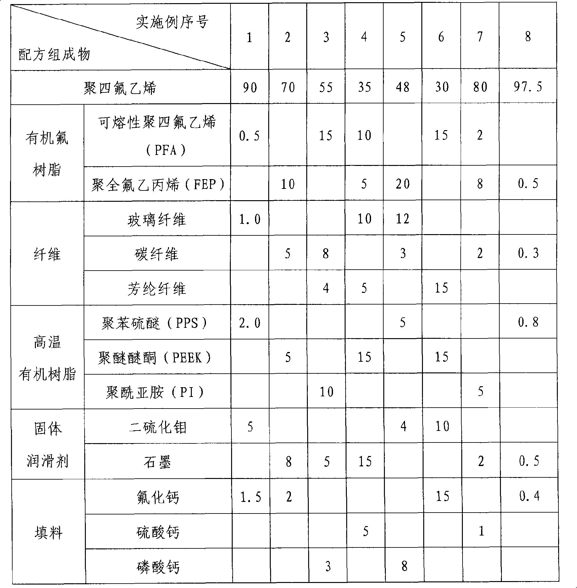
[0022] Mix the components uniformly in a mechanical stirrer according to the ratio in the first column of the surface polymer lubricant implementation formula table, put the uniform mixture into a cylindrical mold for pressing, the molding pressure is 40MPa, hold the pressure 5min, free sintering in a sintering furnace after demoulding, the sintering temperature is 370°C, and the sintering time is 5 hours. After the sintering is completed, it is cooled with the furnace, and the sintered product is mechanically turned into a thin strip with a thickness of 0.15mm; The thickness is 0.25mm, the mesh diameter is 0.20mm, and the diamond-shaped metal braided copper alloy mesh with a side length of 0.35mm is cleaned. The thin strip is laid on the surface of the metal mesh, and the thin strip is embedded with the metal machine by rolling. After sintering, put it in a continuous sintering furnace, and sinter it under the condition of nitrogen protection. The sintering temperature is 380°...

Embodiment 2

[0024] Mix and prepare the polymer material according to the ratio of the second column of the above-mentioned implementation formula table, the specific preparation process is the same as that of Example 1, and the thickness is 0.35mm, and the mesh side length is 0.40mm. After the polygonal stainless steel mesh is cleaned, the thin strip is covered on the surface of the metal mesh, and after the thin strip is mechanically fitted with the metal by rolling, it is placed in a continuous sintering furnace and sintered under nitrogen protection conditions. The temperature is 350°C, the time is 15 minutes, and after being out of the furnace, finish rolling is carried out to obtain a shaft sleeve material with a thickness of 0.45 mm and meeting the tolerance requirements.

Embodiment 3

[0026]Carry out the mixing and preparation of the polymer material according to the ratio of the third row of the above-mentioned surface lubricating material (polymer material) implementation formula table, the specific preparation process is the same as in Example 1, the thickness is 0.45mm, and the mesh diameter is 0.50mm After cleaning the round-hole aluminum alloy mesh formed by punching, the thin strip is covered on the surface of the metal mesh, and the thin strip is mechanically fitted with the metal through rolling, and then placed in a continuous sintering furnace under nitrogen protection conditions. The sintering temperature is 400°C for 15 minutes, and the finish rolling is carried out after being out of the furnace to obtain a composite material with a thickness of 0.50 mm and meeting the tolerance requirements. The material is bonded to a thickness of The bearing material with a thickness of 1.5 mm is formed by finishing rolling on a steel plate of 1 mm. After so...


PUM

PropertyMeasurementUnit
Thicknessaaaaaaaaaa
Mesh sizeaaaaaaaaaa
Granularityaaaaaaaaaa

Abstract

The invention discloses a polymer self-lubrication thin layer composite shaft sleeve and the preparation method, which is rolled by a support skeleton made of metal mesh and a polymer composite. The formation of the metal mesh can be mesh-weaving forming, two-way stretching forming, punch forming or other forming modes; the shape of the mesh can be lozenge, hexagon, round or other shapes. The invention of shaft sleeve has excellent wear resistance, water corrosion resistance and good self-lubricating property and is especially suitable to be applied in the self-lubrication liner bushings of the automobile door hinge, footrest, joy stick and automatic door and window system.

Description

technical field [0001] The invention relates to a polymer self-lubricating thin-layer composite shaft sleeve and a preparation method thereof, in particular to a multi-layer self-lubricating shaft sleeve formed by sintering and rolling metal mesh and polymer composite materials and a preparation method thereof. Background technique [0002] With the rapid development of the automobile industry, higher requirements have been put forward for the performance of the moving friction pair parts. It is required that the material not only has good self-lubricating performance and wear resistance, but also has good high temperature resistance and load resistance. ability. Metal-polymer multilayer composite materials have good thermal conductivity, high load-carrying capacity, excellent wear resistance and self-lubricating properties, and are highly valued by people, and are widely used in automotive connecting rods, shock absorbers and hydraulic cylinders. However, in order to meet ...

Claims


Application Information

Patent Timeline
IPC IPC(8): F16C33/28
Inventor 王宏刚张国强简令奇杨生荣
Owner COB PRECISION PARTS
Why Eureka
Try Eureka