Double quality oscillatory type silicon micro-gyroscopes

A silicon micro-gyroscope and vibrating technology, applied in gyroscope/steering sensing equipment, gyro effect for speed measurement, instrument and other directions, can solve the problems of limited sensitivity, poor linearity of angular vibration, etc., to increase flexibility and release heat Stress, the effect of improving the detection sensitivity

Active Publication Date: 2008-03-05
NANJING UNIV OF SCI & TECH
View PDF0 Cites 44 Cited by
  • Summary
  • Abstract
  • Description
  • Claims
  • Application Information

AI Technical Summary

Problems solved by technology

The dual-mass design of the gyroscope can increase the output signal, but its drive is fully coupled with th...

Method used


Image

  • Double quality oscillatory type silicon micro-gyroscopes
  • Double quality oscillatory type silicon micro-gyroscopes
  • Double quality oscillatory type silicon micro-gyroscopes

Examples


Embodiment Construction

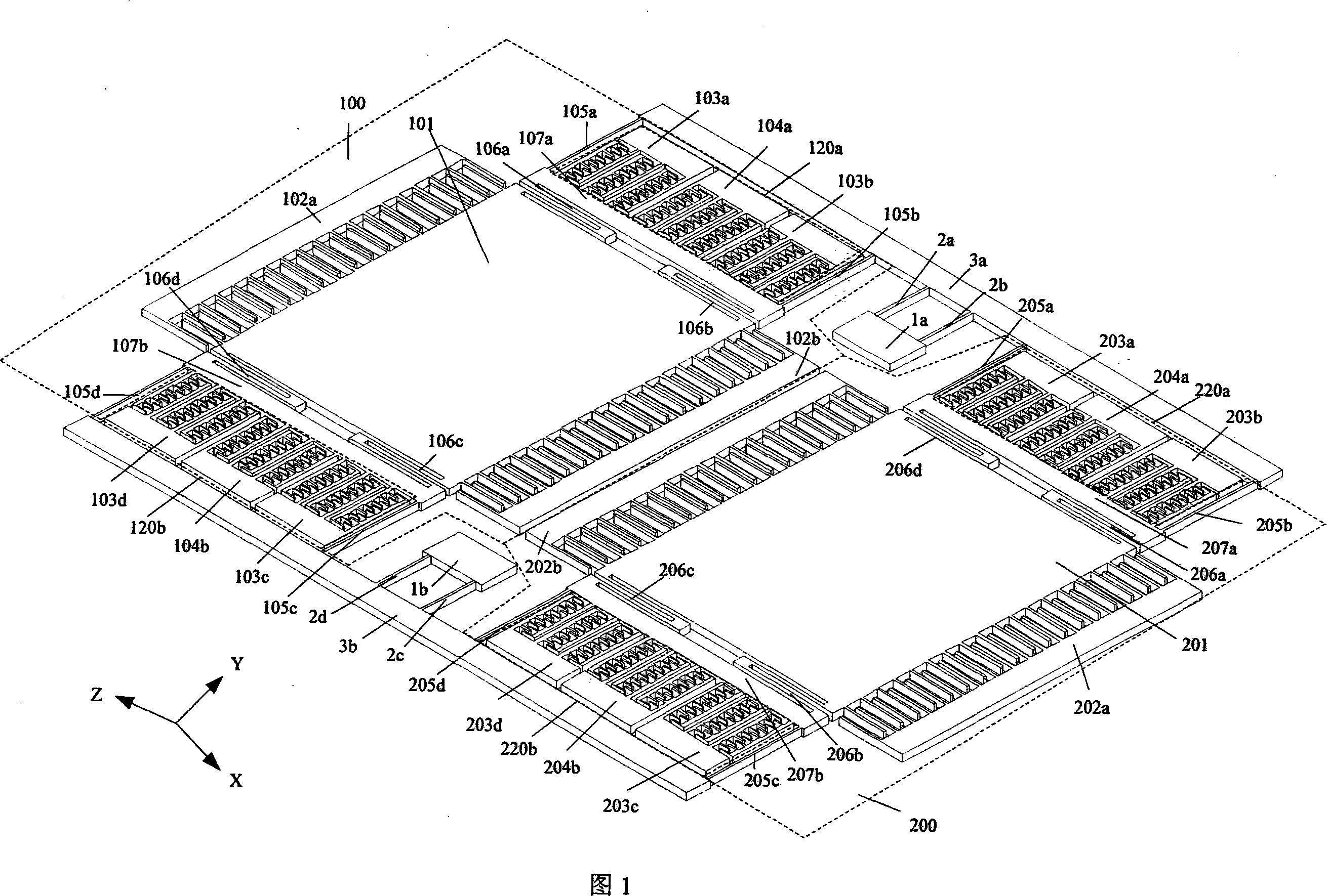
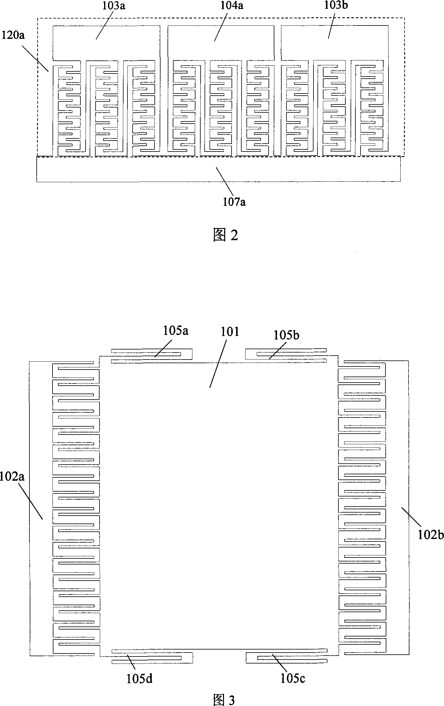
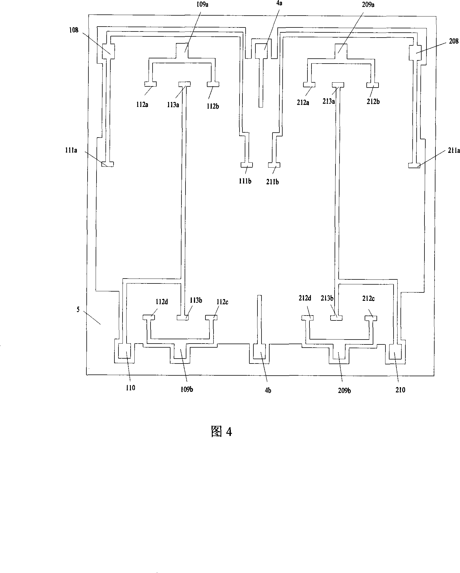
[0013] In conjunction with Fig. 1, the double-mass vibrating silicon micro-gyroscope of the present invention is used to measure a measuring instrument perpendicular to the base level, and consists of upper and lower layers, and the upper layer is a gyroscope mechanical structure made on a single-crystal silicon wafer. The lower layer is the signal leads made on the glass substrate. The upper mechanical structure of the gyroscope is composed of a pair of identical substructures 100, 200. The two substructures 100, 200 are arranged symmetrically on the left and right, and are respectively connected to the beams 3a, 3b. The beams 3a, 3b are connected to the fixed bases 1a, 1b through two groups of torsion bars 2a, 2b, 2c, 2d. The structure of the resonator 120a of the gyroscope is shown in Figure 2, and the resonator 210a consists of three groups of linear combs. Comb-like capacitors. Among them, the middle group is the drive feedback comb, which is composed of the fixed drive f...


PUM


Abstract

The invention comprises an upper layer and a lower layer. On the upper layer there is a gyroscope mechanical structure made on a monocrystalline silicon plate; on the lower layer there are signal leads made on the glass substrate. The gyroscope mechanical structure is composed of two identical substructures; said two substructures are set in bilateral symmetry and respectively connected to the cross beam; the cross beam is connected to the fixed base through two groups of twisted bars; said fixed base is mounted on the linkage point o the fixed base on the glass substrate in order to make the mechanical structure part on the upper layer hang above the glass substrate.

Description

technical field [0001] The invention belongs to micro-electromechanical system and micro-inertia measurement technology, in particular to a double-mass vibrating silicon micro-gyroscope. Background technique [0002] Micromachined inertial instruments include micromachined gyroscopes (MMG) and micromachined accelerometers (MMA). The use of microelectronic processing technology allows the complete integration of micromechanical structures and required electronic circuits on a silicon chip, thereby achieving a high degree of unity in terms of performance, price, volume, weight, and reliability. Therefore, this type of instrument has a series of advantages (such as small size, light weight, cheap price, high reliability, mass production, etc.), and has broad application prospects in both military and civilian fields. In civilian use, it is mainly used in the automotive industry, industrial monitoring and consumer products and robotics, such as airbags, anti-lock braking system...

Claims


Application Information

Patent Timeline
IPC IPC(8): G01C19/56B81B7/02G01P9/04G01P15/097G01C21/18G01C19/5656
Inventor 裘安萍施芹苏岩朱欣华
Owner NANJING UNIV OF SCI & TECH
Why Eureka
Try Eureka