Automatic tuning control F-P fiber optic sensor

An optical fiber sensor and automatic tuning technology, applied in the field of optical fiber sensing, can solve problems such as expensive, weak light, and bulky systems

Inactive Publication Date: 2008-03-05
SHANGHAI INST OF OPTICS & FINE MECHANICS CHINESE ACAD OF SCI
View PDF1 Cites 29 Cited by
  • Summary
  • Abstract
  • Description
  • Claims
  • Application Information

AI Technical Summary

Problems solved by technology

However, this method will encounter noise caused by external interference (parasitic F-P effect) brought by the narrow linewidth of the external cavity laser, and the external cavity laser used in this method will make the system bulky and expensive, and does not consider the laser Due to the change of light intensity and the influence of signal generation on interference, an oscilloscope is also used in this tuning process, which limits the practicality of this method
[0005] In the "Fiber Optic Acoustic Sensor" (Cai Haiwen, etc.) whose patent number is ZL200610024955, the acoustic sensor adopts the solution of broadband light source + tunable filter to obtain a light source with a line width of about 1nm. If the filter is reliable in this method, stable It is suitable for the light source of F-P sensor head, but the disadvantage of this method is also obvious, except that the tunable filter is generally more expensive, and the light after the broadband and tunable filter is generally relatively weak, which will cause System Sensitivity Decrease

Method used


Image

  • Automatic tuning control F-P fiber optic sensor
  • Automatic tuning control F-P fiber optic sensor
  • Automatic tuning control F-P fiber optic sensor

Examples


Embodiment Construction

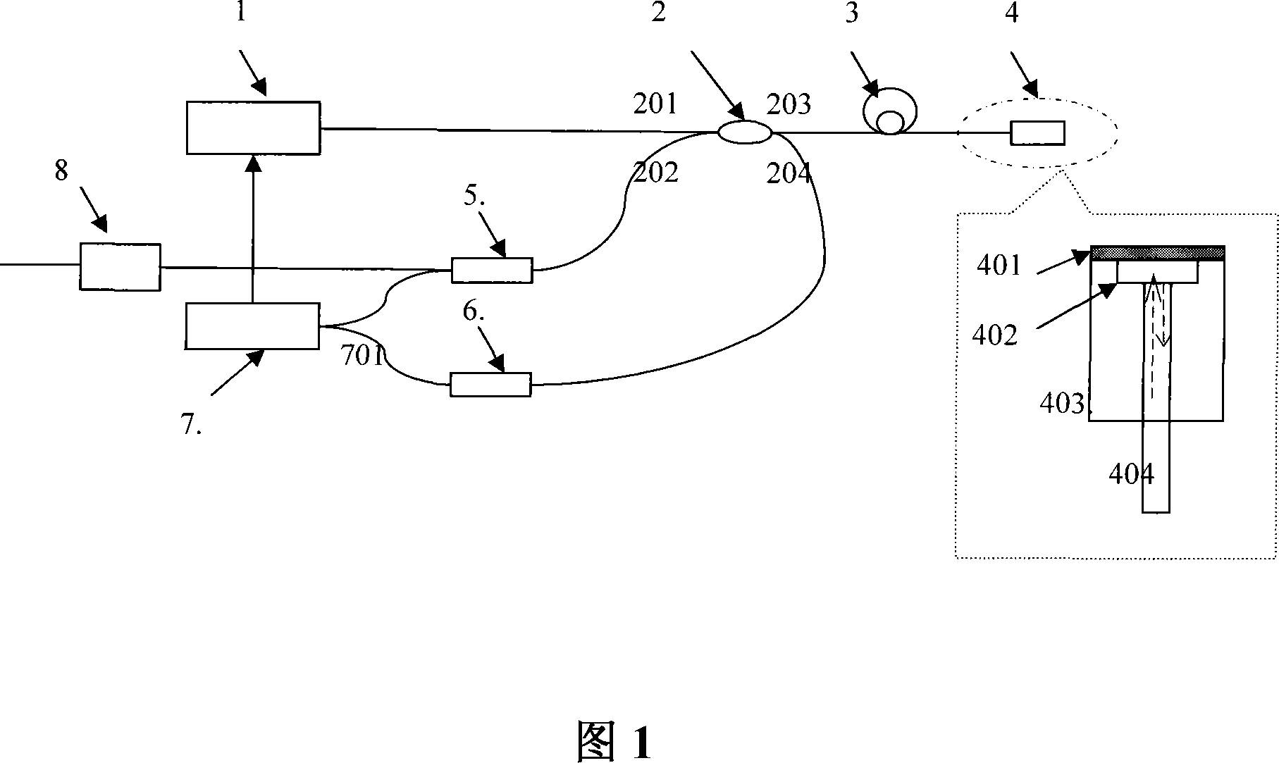
[0035]Please refer to Fig. 1 first. Fig. 1 is a schematic structural diagram of the automatic tuning F-P optical fiber sensor of the present invention, which is also a structural schematic diagram of an embodiment of the present invention. As can be seen from the figure, the automatic tuning F-P optical fiber sensor of this embodiment includes a light source 1 and a sensing head 4 , the light source 1 is a distributed feedback single-mode semiconductor laser with a temperature control circuit, the laser is connected to the first port 201 of the coupler 2 through an optical fiber, and the third port 203 of the coupler 2 is connected to the The sensing head 4, the fourth port 204 of the coupler 2 is connected to the active control unit 7 through the second photodetector 6, the second port 202 of the coupler 2 is connected to the input port of the first photodetector 5, The output end of the first photodetector 5 is respectively connected to the active control unit 7 and the signa...


PUM

PropertyMeasurementUnit
lengthaaaaaaaaaa
reflectanceaaaaaaaaaa

Abstract

The invention comprises a light source and a sensing head. The light source comprises a laser with a temperature control circuit. The laser is connected to a first port of the coupler through optical fiber; the third port of the coupler is connected to the sensing head through optical fiber; the fourth port of the coupler is connected to the initial control unit through second photo detector; the second port of the coupler is connected to the input port of the first photo detector; the output port of the first photo detector is respectively connected to the active control unit and the signal output unit; the output end of the active control unit is connected to the temperature control circuit. Said sensing head comprise a F-P cavity; both sides of the F-P cavity are respectively connected to the silicon membrane and optical fiber; said silicon membrane, F-P cavity and optical fiber is secured by a quartz case; the other end of the optical fiber is connected to said mono-mode fiber.

Description

technical field [0001] The invention relates to optical fiber sensing, which is a high-sensitivity working point (abbreviated as Q point) stable fiber optic displacement / vibration sensor. In particular, it involves the use of a coated F-P cavity and a sensor system that uses a certain cavity length to obtain the maximum contrast of fringes with low-precision interference, controls the wavelength of the tunable laser through signal output feedback, and then locks the Q value point of the system. The invention is suitable for measuring the displacement, pressure, ultrasonic wave and the like in places where the ambient temperature or the external medium is unstable. Background technique [0002] Until recently, pressure sensors, such as vibration sensors, were based on capacitive or piezoresistive structures. This structure has many disadvantages, such as low sensitivity, high bias voltage, insulation between layers, consistency between membrane electrodes, etc., all of whic...

Claims


Application Information

Patent Timeline
Patent Type & Authority Applications(China)
IPC IPC(8): G01D5/353G01H9/00G01L1/24G01L11/02G02B6/42G02B6/36
Inventor 陈建永陈迪俊蔡海文耿健新方祖捷
Owner SHANGHAI INST OF OPTICS & FINE MECHANICS CHINESE ACAD OF SCI
Why Eureka
Try Eureka