
Dye-sensitized photoelectric conversion element, its manufacturing method, electronic device, its manufacturing method and electronic apparatus

A dye-sensitized and photoelectric conversion element technology, which is applied in the field of electronic equipment and dye-sensitized solar cells, can solve the problems of unsatisfactory durability of solar cells and low photoelectric conversion efficiency of solar cells

Inactive Publication Date: 2008-03-05
SONY GRP CORP
View PDF1 Cites 4 Cited by
  • Summary
  • Abstract
  • Description
  • Claims
  • Application Information

AI Technical Summary

Problems solved by technology

However, the photoelectric conversion efficiency of such solar cells is as low as 1% or less, and the durability of such solar cells is also unsatisfactory

Method used


Image

  • Dye-sensitized photoelectric conversion element, its manufacturing method, electronic device, its manufacturing method and electronic apparatus
  • Dye-sensitized photoelectric conversion element, its manufacturing method, electronic device, its manufacturing method and electronic apparatus
  • Dye-sensitized photoelectric conversion element, its manufacturing method, electronic device, its manufacturing method and electronic apparatus

Examples


preparation example Construction

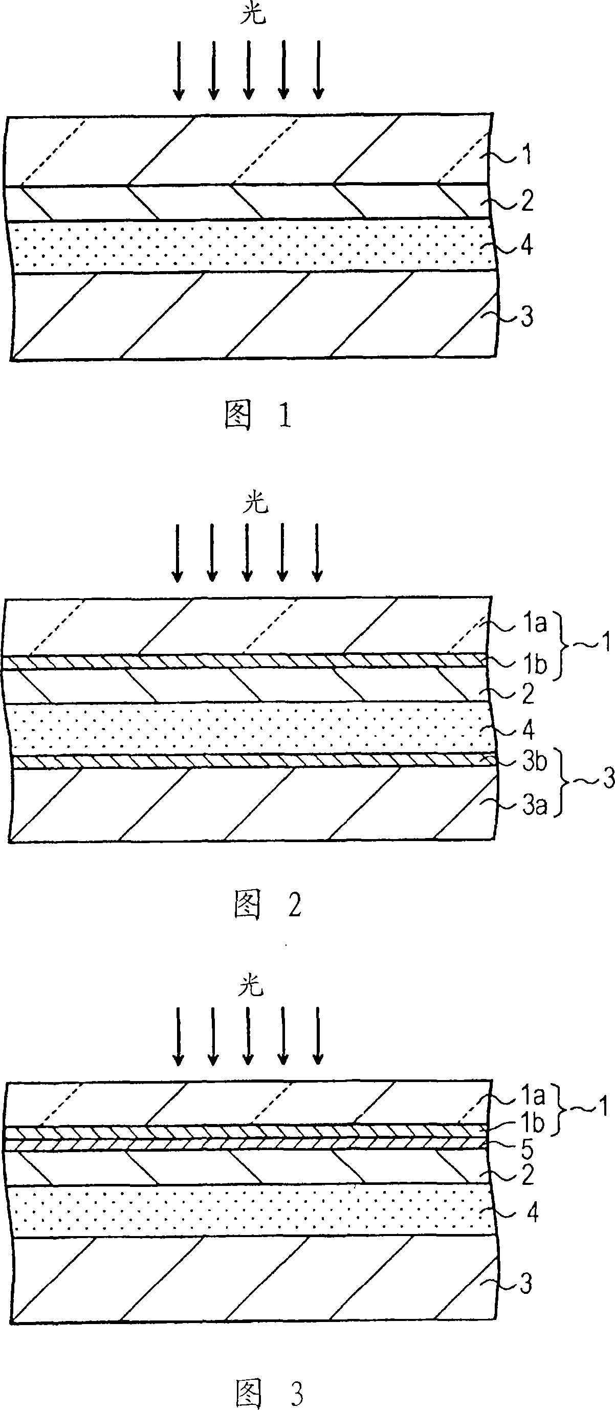
[0063] A method of producing the dye-sensitized photoelectric conversion element will now be described.

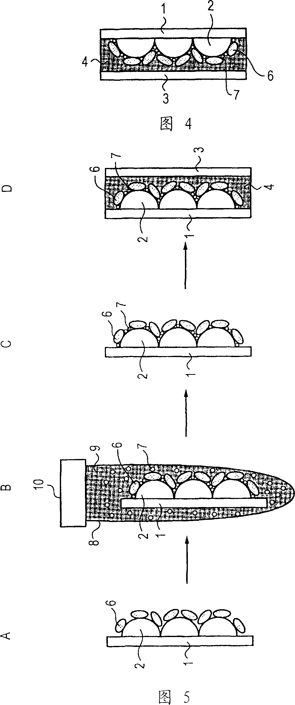
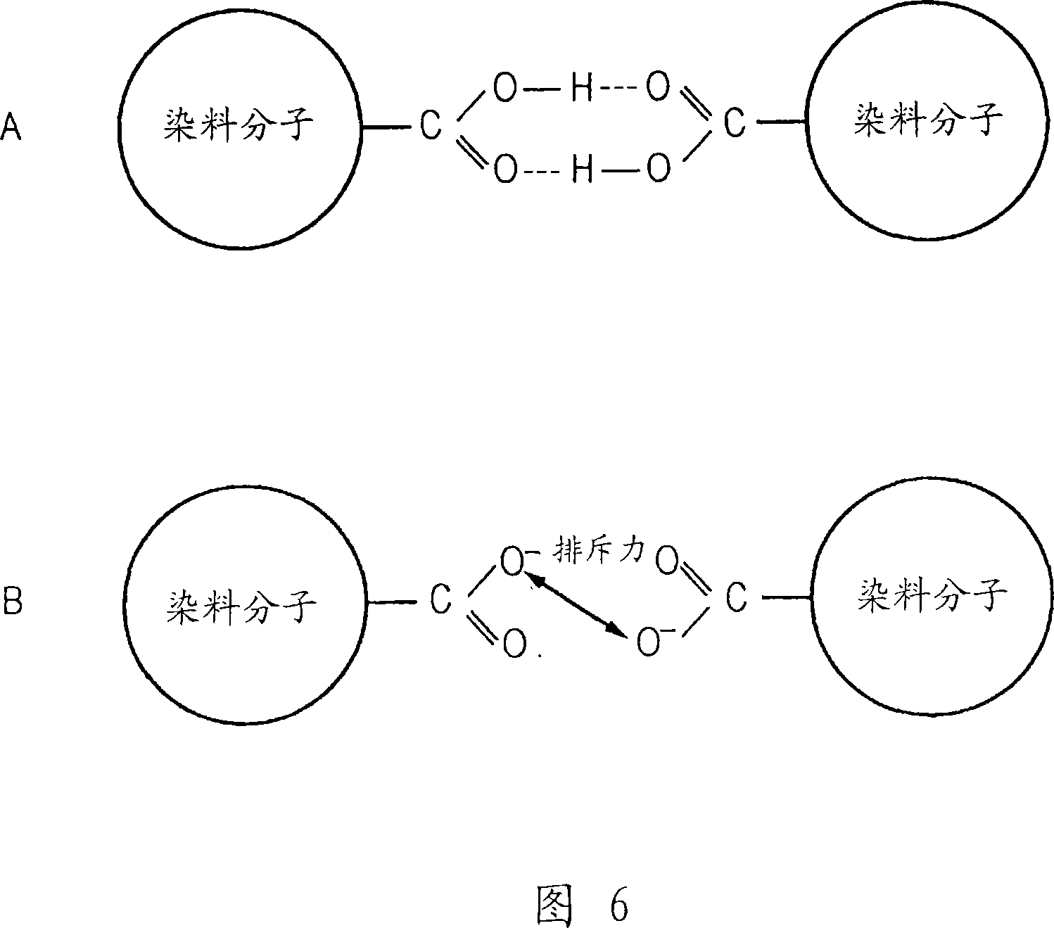
[0064] First, a transparent conductive substrate 1 is prepared. Next, a paste containing dispersed semiconductor fine particles is applied onto the transparent conductive substrate 1 with a predetermined gap (thickness). The resulting transparent conductive substrate 1 is heated to a predetermined temperature to sinter the semiconductor fine particles. The transparent conductive substrate 1 having the sintered semiconductor fine particles is immersed in a dye solution or the like, so that the semiconductor fine particles carry the dye. In the pigment solution, part of the acid functional groups of the sensitizing pigment molecules are pre-neutralized with a basic compound to form an anion, and the basic compound contains at least one selected from Li, Na, K, tetramethylammonium, tetraethylammonium, tetramethylammonium, Hydroxides of metals or compounds in propylammonium,...

Embodiment 1

[0072] Use TiO 2 The fine particles are semiconductor fine particles. Prepared according to literature 4 containing dispersed TiO 2 The fine particle paste is as follows. At room temperature, gradually add 125 ml of titanium isopropoxide dropwise to 750 ml of 0.1 M aqueous nitric acid solution with constant stirring. After the dropwise addition was completed, the solution was moved to a thermostat at 80° C., and then stirred for 8 hours to obtain a white translucent sol solution. The solution was cooled to room temperature, filtered through a glass filter, and diluted to 700ml. The resulting sol solution was transferred to an autoclave, subjected to hydrothermal treatment at 220° C. for 12 hours, and ultrasonicated for 1 hour for dispersion. The resulting solution was evaporated and concentrated with an evaporator at 40 °C to make the TiO 2 The content is 20% by weight. Adding paste-based TiO to the concentrated sol solution 2 20% by weight of polyethylene glycol (molec...

Embodiment 2 to 10

[0082] Dye-sensitized photoelectric conversion elements were prepared in accordance with the method in Example 1 except that the dyes and basic compounds shown in Table 1 were used.


PUM

PropertyMeasurementUnit
conversion efficiencyaaaaaaaaaa
particle diameteraaaaaaaaaa

Abstract

In a dye-sensitized photovoltaic device including a semiconductor fine particle layer 2 on which a sensitizing dye is adsorbed, a counter electrode 3, and an electrolyte layer 4 between the electrodes, a molecule having a plurality of acid functional groups for adsorption onto the semiconductor electrode is used as a molecule of the sensitizing dye, and part of the acid functional groups is neutralized with an alkaline compound which is a hydroxide of at least one metal or compound selected from the group consisting of Li, Na, K, tetramethylammonium, tetraethyl ammonium, tetrapropyl ammonium, tetrabutyl ammonium, an imidazolium compound, and a pyridinium compound. In this manner, a dye-sensitized photovoltaic device that can achieve high photoelectric conversion efficiency even in the cases where a dye containing readily aggregating acid functional groups, such as carboxylic acid, as the adsorbing groups is used. A method for making the device is also provided.

Description

technical field [0001] The present invention relates to a dye-sensitized photoelectric conversion element (dye-sensitized photovoltaicdevice), a preparation method of the element, an electronic device, a preparation method of the device, and an electronic apparatus (electronic apparatus). For example, the present invention is applicable to a dye-sensitized solar cell including a semiconductor electrode composed of dye-carrying semiconductor fine particles. Background technique [0002] It is recognized that the use of fossil fuels such as coal and petroleum as energy sources causes global warming due to the carbon dioxide produced therefrom. If nuclear energy is used, then there is a risk of radioactive contamination. As environmental issues are now more discussed, the reliance on the aforementioned energy sources presents many problems. [0003] In contrast, a solar cell, a photoelectric conversion element that converts sunlight into electricity, uses sunlight as an energ...

Claims


Application Information

Patent Timeline
Patent Type & Authority Applications(China)
IPC IPC(8): H01M14/00H01L31/04
CPCY02E10/542H01L51/0086Y02T10/7022H01G9/2004H01G9/2059H01M14/005H01G9/2031Y02E10/549Y02T10/70H10K85/344H01M14/00H01L31/04
Inventor 诸冈正浩小仓丽子铃木佑辅
Owner SONY GRP CORP
Learn More