
Heat radiator and surface treating method thereof

A technology of heat dissipation device and surface treatment, applied in the field of heat dissipation device and surface treatment thereof, can solve the problems of poor heat dissipation performance of ceramic materials, limitation of improvement of heat dissipation efficiency, and high cost of carbon nanotubes, and achieves low cost, high heat dissipation efficiency, and ease of use. The effect of the operation

Inactive Publication Date: 2008-04-09
BOE TECH GRP CO LTD
View PDF8 Cites 9 Cited by
  • Summary
  • Abstract
  • Description
  • Claims
  • Application Information

AI Technical Summary

Problems solved by technology

[0004] But the problem that above-mentioned prior art scheme exists is: carbon nanotube has the problems such as high cost, complex process and easy lodging; And utilize porous ceramics as heat sink, the heat dissipation performance of ceramic material is relatively poor, has greater effect to the raising of heat dissipation efficiency. limit

Method used


Image

  • Heat radiator and surface treating method thereof
  • Heat radiator and surface treating method thereof
  • Heat radiator and surface treating method thereof

Examples


Embodiment 2

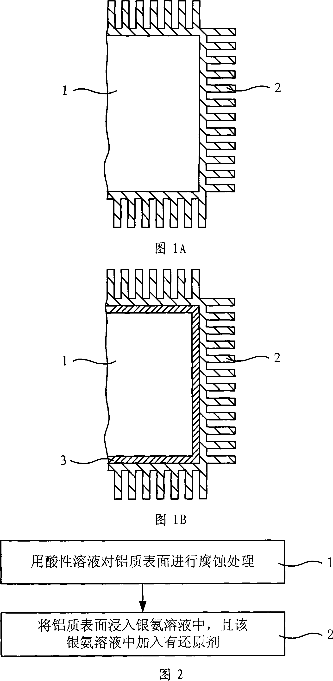
[0024] As shown in Figure 1B, it is a schematic structural diagram of a second embodiment of the heat dissipation device of the present invention. The heat dissipation device includes a heat dissipation body 1, and the material of the heat dissipation body 1 is other metal materials other than aluminum. A layer of aluminum film 3, on the surface of the aluminum film 3 of the heat dissipation body 1, silver micron clusters 2 are attached.

[0025] In this embodiment, the thickness of the aluminum film should be at least 1 micron (μm), preferably an aluminum film with a thickness of 50 μm. According to needs, the aluminum film can be plated only on the heat dissipation surface where silver micro clusters need to be formed.

[0026] In the technical solutions of embodiment one and embodiment two of the heat dissipation device of the present invention, silver micron clusters are further attached to the outer surface of the heat dissipation body, which is equivalent to increasing t...

Embodiment 3

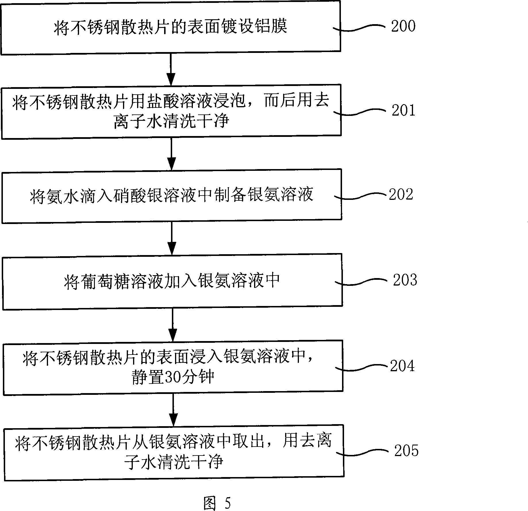
[0043] As shown in Figure 5, it is the flow chart of the third embodiment of the surface treatment method of the heat dissipation device of the present invention. This embodiment carries out surface treatment for stainless steel heat sinks, which includes the following steps:

[0044] Step 200, plating an aluminum film with a thickness of 50 microns on the surface of the stainless steel heat sink by electroplating;

[0045] Step 201, immerse the stainless steel radiator plated with the aluminum film in a hydrochloric acid solution with a concentration of 1.0 mol / L for 1 minute for corrosion treatment, then take it out, and clean it with deionized water;

[0046]Step 202, drip ammonia water with a concentration of 1.1 mol / L into 20 mL of a silver nitrate solution with a concentration of 0.12 mol / L, and titrate until the silver hydroxide (AgOH) precipitate disappears, thereby preparing a silver ammonia solution;

[0047] Step 203, adding 30ml of glucose solution with a concentra...


PUM

PropertyMeasurementUnit
thicknessaaaaaaaaaa
thicknessaaaaaaaaaa

Abstract

The invention relates to a radiation device and a surface processing method. The radiation device includes a radiation body, wherein, the radiation body is made of aluminum material or the outer surface is provided with an aluminum film; the aluminum surface of the radiation surface is attached with silver micron cluster. The surface processing method of the radiation device includes the following steps: use acid solution to perform corrosion processing on the aluminum surface of the radiation body; and immerge the aluminum surface after corrosion processing into silver amine solution, which contains a reducing agent for silver ions exchange. The invention improves the radiation efficiency, because of large radiation surface area attached with silver micron cluster and large silver thermal coefficient. The radiation device surface processing method of the invention has the advantages of convenient and simple process course and easy operation realization.

Description

technical field [0001] The invention relates to a heat dissipation device and a surface treatment method thereof, in particular to a heat dissipation device in the form of a heat dissipation fin or a heat dissipation pipe, and a method for treating the surface thereof. Background technique [0002] With the development of electronic technology, various chips are increasingly miniaturized and high-speed, so higher requirements are put forward for heat dissipation. How to improve the heat dissipation effect of heat sinks has always been the focus of research by various manufacturers. At present, in addition to the common air cooling methods, water cooling and heat pipe cooling methods are gradually being widely used. The thermal conductivity and heat transfer area of ​​the heat dissipation material are important factors affecting the heat dissipation efficiency of the heat sink. Taking the CPU heat sink as an example, larger heat sink size and more heat dissipation fins can in...

Claims


Application Information

Patent Timeline
Patent Type & Authority Applications(China)
IPC IPC(8): H05K7/20H01L23/373C23G1/12C23C18/44
Inventor 张卓何璇李琳李宏彦
Owner BOE TECH GRP CO LTD
Learn More