
In situ combustion slug and steam driving combined type crude oil producing method

A technology of burning oil layers and steam flooding, which is applied in the direction of production fluid, earthwork drilling, wellbore/well components, etc. It can solve the problems of large water storage in a single well and low oil recovery rate, so as to save investment costs and shorten the time Effect

Inactive Publication Date: 2011-07-06
富象油气技术服务有限公司
View PDF1 Cites 0 Cited by
  • Summary
  • Abstract
  • Description
  • Claims
  • Application Information

AI Technical Summary

Problems solved by technology

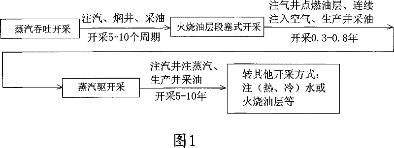
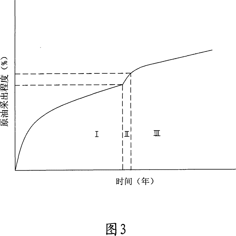
[0006] The main purpose of the present invention is to overcome the defects of large single well water storage and low crude oil recovery after steam huff and puff production, and to provide a new method of burning oil layers after steam huff and puff and before steam flooding. The method of plug mining and then turning to steam flooding to extract crude oil belongs to the method of extracting crude oil in three ways, that is, the combined mining method. The technical problem to be solved is that the combustion zone of the oil layer slug can generate a high temperature of 400 ° C to 800 ° C, which is conducive to the stimulation of vaporization steam. Exploitation and storage of water is beneficial to increase the bottom hole temperature of the steam injection well, to increase the dryness of the bottom steam after steam flooding, to increase the pressure of the oil layer, to establish a large production pressure difference, to increase the displacement of the oil well, and to increase the steam Improve the production-injection ratio during the flooding production period, shorten the initial low-production period of steam flooding, and improve the effect of steam flooding

Method used


Image

  • In situ combustion slug and steam driving combined type crude oil producing method
  • In situ combustion slug and steam driving combined type crude oil producing method
  • In situ combustion slug and steam driving combined type crude oil producing method

Examples


Embodiment 1

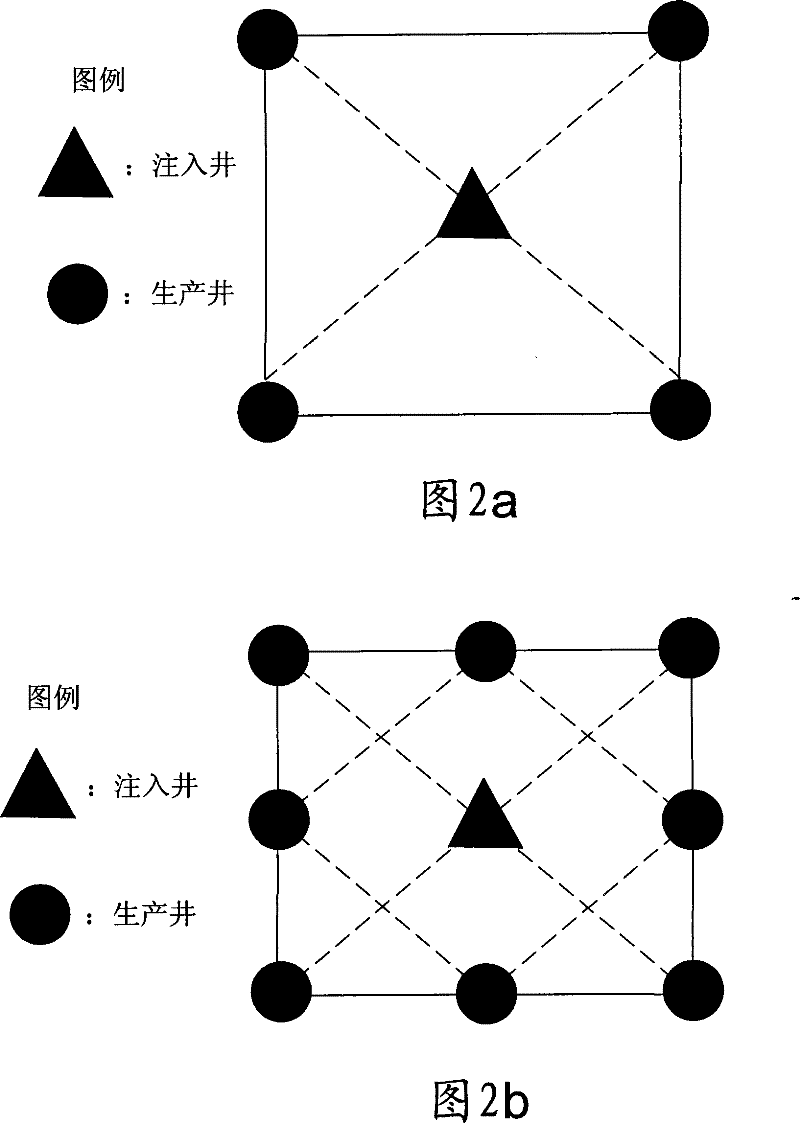
[0038] The buried depth of oilfield 1 is 600-1000m, the effective thickness of oil layer is 20.0m, the ratio of net to total thickness is 0.5, the average porosity is 25%, the average permeability is 500md, the coefficient of variation of permeability is 0.8, and the viscosity of crude oil under oil layer conditions is 120mPa .s.

[0039] 1) Carry out rough screening according to the geological characteristics and development status of the oilfield. The reservoir meets the following conditions: reservoir depth 0.50, total reservoir thickness>10.0m, net-to-total thickness ratio>0.5, reservoir porosity>0.2, permeability variation coefficient200md , the viscosity of crude oil under oil layer conditions <20000mPa.s;

[0040] 2) First, the steam huff and puff is used to exploit the oil reservoir. The well pattern is a square well pattern, the well spacing can be 150m, and the steam is injected into the well continuously according to the steam injection intensity of 100t / m. , cont...

Embodiment 2

[0044] The buried depth of oil field 2 is 1500-1600m, the effective thickness of the oil layer is 60.0m, the net total thickness ratio is 0.8, the average porosity is 25%, the average permeability is 1200md, and the viscosity of crude oil under the oil layer conditions is 510mPa.s.

[0045] 1) Carry out rough screening according to the geological characteristics and development status of the oilfield. The reservoir meets the following conditions: reservoir depth 0.50, total reservoir thickness>10.0m, net-to-total thickness ratio>0.5, reservoir porosity>0.2, permeability variation coefficient200md , the viscosity of crude oil under oil layer conditions <20000mPa.s;

[0046] 2) Firstly, the steam huff and puff is used to exploit the oil reservoir. The well pattern is a square well pattern, and the well spacing can be 105m. The steam is continuously injected into the well according to the steam injection intensity of 100t / m. After the well is soaked for 7 days, the heat can be di...

Embodiment 3

[0050] The buried depth of the oil reservoir in oil field 3 is 1000-1500m, the effective thickness of the oil layer is 40.0m, the net total thickness ratio is 0.46, the average porosity is 23%, the average permeability is 400md, the coefficient of variation of permeability is 0.7, and the viscosity of crude oil under the oil layer condition is 2000mPa .s.

[0051] 1) Carry out rough screening according to the geological characteristics and development status of the oilfield. The reservoir meets the following conditions: reservoir depth 0.50, total reservoir thickness>10.0m, net-to-total thickness ratio>0.5, reservoir porosity>0.2, permeability variation coefficient200md , Crude oil viscosity under oil reservoir conditions <10000mPa.s;

[0052] 2) First, the steam huff and puff is used to exploit the oil reservoir. The well pattern is a square well pattern, and the well spacing can be 120m. The steam is continuously injected into the well according to the steam injection inten...


PUM


Abstract

The present invention discloses a method of oil pumping which adopts the combination of fire oil layer slug and steam drive before steam soaking and is applicable for the pumping of thick oil reservoir. After the steam soaking of the thick oil reservoir and before the pumping of the steam drive, the fire oil layer slug type pumping is performed; an ignition technology is adopted to ignite the oil layer to burn; an air compressor is used to inject air into the oil layer continuously from a center injection well; after 0.3 to 0.8 years of pumping, steam is injected into the oil layer through an injection well, and the steam drive type pumping is performed. The invention can generate the high temperature of 400 to 800 DEG C in the burning zone of the fire oil layer slug, which is in favor of the water stored in an individual well after the steam soaking to be vaporized as high-dryness steam; the temperature of the bottom of the injection well, and the dryness of the steam injected by the following steam drive are improved; the strata pressure is improved; larger producing pressure differential is achieved, which is in favor of improving the lifting rate of the oil well; moreover, the invention is in favor of shortening the low-production period at the beginning period of the steam drive and improving the developing effects of the steam drive and the recovery ratio of crude oil.

Description

technical field [0001] The present invention relates to a mining technology for heavy oil reservoirs, in particular to a combination of steam huff and puff followed by fire oil layer slug and steam flooding before exploitation of incinerated oil layers in heavy oil reservoirs. Methods of extracting crude oil. Background technique [0002] A commonly used method in petroleum exploitation is steam injection thermal recovery, which is only used for heavy oil reservoirs with high viscosity and poor fluidity, that is, reservoirs with crude oil viscosity greater than 50mPa.s under the conditions of oil layer temperature and crude oil containing dissolved gas. Steam huff and puff thermal recovery is to continuously inject a certain amount of steam into a production well in a short period of time, shut down the well for several days, and then start the well for production. Due to the short steam injection time, quick effect and good economic benefits, steam huff and puff is often u...

Claims


Application Information

Patent Timeline
Patent Type & Authority Patents(China)
IPC IPC(8): E21B43/243E21B43/24
Inventor 张锐朴晶明邓明
Owner 富象油气技术服务有限公司
Learn More