Split graphite crucible and method for preparing carbon coating inside the crucible

A graphite crucible and inner coating technology, applied in coating, crucible furnace, metal material coating process and other directions, can solve the problems of low carbon mobility of coating materials, and achieve easy automation, small thermal impact and moderate cost. Effect

Inactive Publication Date: 2008-04-16
BEIHANG UNIV
View PDF0 Cites 21 Cited by
  • Summary
  • Abstract
  • Description
  • Claims
  • Application Information

AI Technical Summary

Problems solved by technology

[0008] (4) The carbon mobility

Method used


Image

  • Split graphite crucible and method for preparing carbon coating inside the crucible
  • Split graphite crucible and method for preparing carbon coating inside the crucible

Examples


Embodiment 1

[0055] Embodiment one: Made with 100μm thick Y 2 o3 Carbon barrier coating

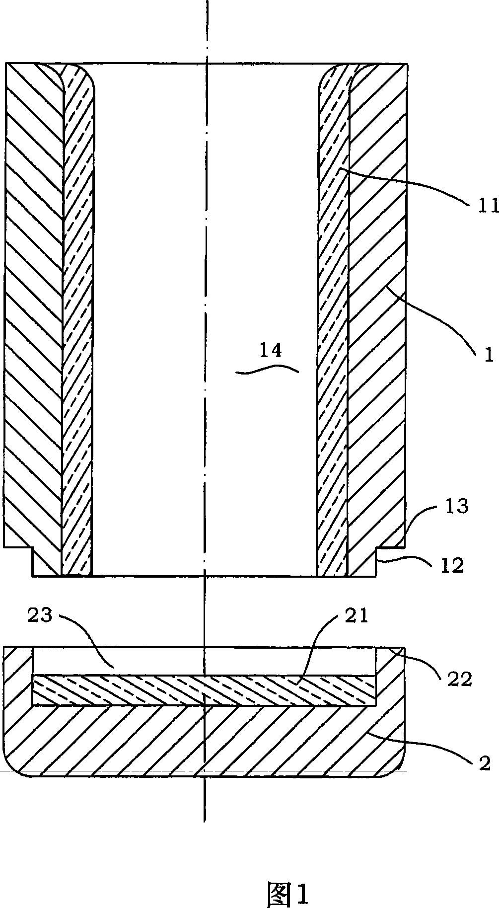
[0056] Referring to the split graphite crucible structure shown in Fig. 1, the inner diameter of an upper crucible body 1 is 100 mm, the thickness of the boss 12 is 10 mm, and the inner diameter of the lower crucible body 12 is 120 mm. The boss 12 of the upper pot body 1 is installed in the concave cavity 23 of the lower pot body 12, and the end surface of the boss 12 is closely connected with the bottom surface of the concave cavity 23 of the lower pot body 2, and the convex table surface 13 of the upper pot body 1 is in contact with the lower pot body. The concave support surface 22 of the body 2 is closely engaged.

[0057] Next, the atmospheric plasma spraying method will be used to prepare 100 μm thick Y on the inner wall of the crucible. 2 o 3 Carbon barrier coating, its preparation steps include:

[0058] The first step: making yttrium oxide (Y 2 o 3 ) particles

[0059] (A) Prepare the...

Embodiment 2

[0085] Embodiment two: Made with 250μm thick Y 2 o 3 Carbon barrier coating

[0086] Referring to the split graphite crucible structure shown in Fig. 1, an upper crucible body 1 and a lower crucible body 2 are manufactured by mechanical processing.

[0087] Next, the atmospheric plasma spraying method will be used to prepare 250 μm thick Y on the inner wall of the crucible. 2 o 3 carbon barrier coating,

[0088] Its preparation steps are:

[0089] The first step: making yttrium oxide (Y 2 o 3 ) particles

[0090] (A) Prepare the first mixture

[0091] The first mixture is made up of yttrium oxide powder, gum arabic, ammonium citrate and deionized water, and its consumption is to add gum arabic 30g, ammonium citrate 20g, deionized water 900g in every 1000g of yttrium oxide powder;

[0092] The yttrium oxide powder has a purity of 99.99% and a particle size of 0.1-10 μm;

[0093] (B) ball milling slurry,

[0094] Put the first mixture in step (A) into a ball mill (s...


PUM

PropertyMeasurementUnit
Particle sizeaaaaaaaaaa

Abstract

The invention discloses a split type graphite crucible with a split structure and Y2O3 carbon coating with zero resistance in upper and lower crucible bodies, wherein, a lug boss (12) of the upper crucible body (1) of the split type graphite crucible is arranged inside a concave chamber (23) of the lower crucible body (2), the end surface of the lug boss (12) is in close joint with the bottom of the concave chamber (23) of the lower crucible body (2), a surface of the lug boss (12) of the upper crucible body (1) is in close joint with a concave support surface (22) of the lower crucible body (2); the wall of an inner chamber (14) of the upper crucible body (1) is provided with an A-type inner coating (11) with a thickness of 50-250 um, the bottom of the concave chamber (23) of the lower crucible body (2) is provided with a B-type inner coating (21) with a thickness of 50-250 um. Both the A-type inner coating (11) and the B-type inner coating (21) adopt the spraying method of air plasma to prepare Y2O3 inside the crucible body of the split type graphite crucible so as to form the carbon coating with zero resistance, which effectively stops the chemical reaction between carbon and metal fused mass in the melting process, thereby avoiding carbon pollution.

Description

technical field [0001] The present invention relates to a kind of processing vessel used for smelting high-melting-point alloys, more specifically, refers to a graphite crucible with a split structure, and Y 2 o 3 The method of carbon barrier coating. Background technique [0002] At present, water-cooled copper crucibles are usually used for smelting high-melting point alloys with high content of highly active elements such as Ti and Nb. The characteristics of this type of crucible are that copper itself has a low melting point and poor high-temperature strength, and it needs to be cooled by circulating water when used. However, circulating water cooling often results in uneven temperature of the alloy liquid in the molten pool, low degree of superheat, poor composition uniformity of the melt, and ultimately affects the performance of the material. In order to change this situation, a lot of manpower and material resources have been invested at home and abroad to develop ...

Claims


Application Information

Patent Timeline
IPC IPC(8): F27B14/10C04B41/61C22C1/02C23C4/10C23C4/11C23C4/134
Inventor 张虎龚路杰田洪超徐惠彬
Owner BEIHANG UNIV
Why Eureka
Try Eureka