A solar component and its encapsulation method and special encapsulation tool

A technology of solar modules and encapsulation methods, which is applied in the field of solar cells, can solve problems such as undisclosed connection methods between solar cells and PCB boards, unfavorable installation of solar cell panels, and malfunction of equipment, so as to speed up curing efficiency and reduce area , the effect of easy operation

Inactive Publication Date: 2008-04-30
BEIJING HI TECH WEALTH INVESTMENT DEV
View PDF1 Cites 6 Cited by
  • Summary
  • Abstract
  • Description
  • Claims
  • Application Information

AI Technical Summary

Problems solved by technology

In this patent, simply arranging a plurality of solar cells together without restricting the arrangement, then there must be the possibility of irregular arrangement, and this irregularity may be displayed to a greater extent in the The upper surfaces of the above-mentioned multiple solar cells are not on the same horizontal plane, so the solar cell panels in this form are not conducive to their installation in electronic devices such as mobile phones, and the market utilization rate is very low.
In addition, the patent does not disclose the connection method between the plurality of solar cells and the PCB board. In the prior art, a large-area welding process is often used to realize the connection between the solar cells and the PCB board. During the process, since the pads of the PCB board and the expansion coefficients of the solder paste are different, it is easy to cause the fragmentation of the solar cells
The most important thing is that in the prior art, when a plurality of solar cells are packaged on the PCB board, the electrode leads drawn from the main grid line of each solar cell and connected to the PCB board are all Single lead wire, for this kind of lead wire design, once the lead wire is damaged, it will cause the paralysis of the entire solar cell, resulting in the failure of the device to work normally

Method used


Image

  • A solar component and its encapsulation method and special encapsulation tool
  • A solar component and its encapsulation method and special encapsulation tool
  • A solar component and its encapsulation method and special encapsulation tool

Examples


Embodiment Construction

[0029] The present invention will be further described below with reference to the accompanying drawings and embodiments, but it should be noted that these embodiments are only used to illustrate the components, tools and methods described in the present invention, rather than limiting the scope of the present invention thereto.

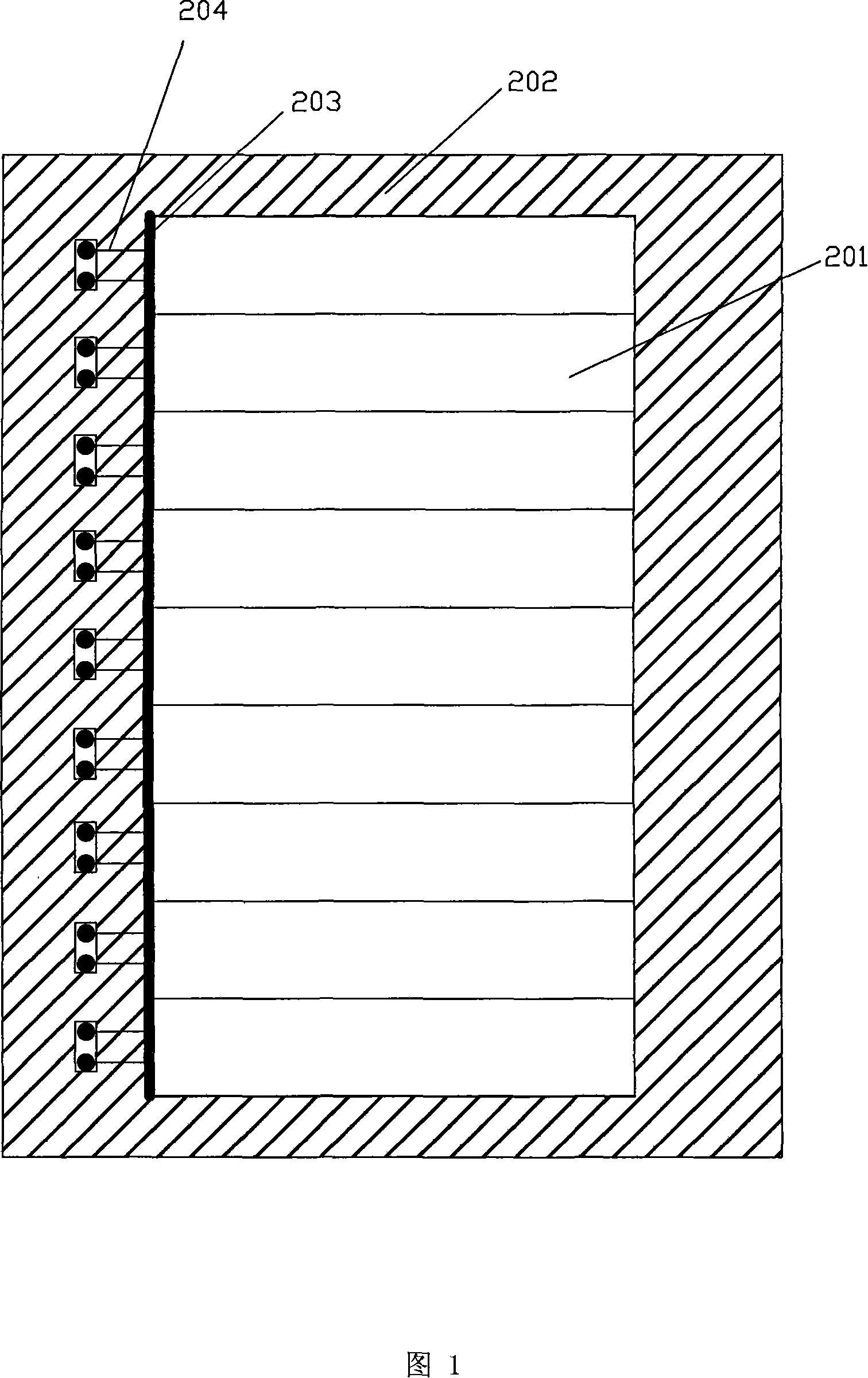
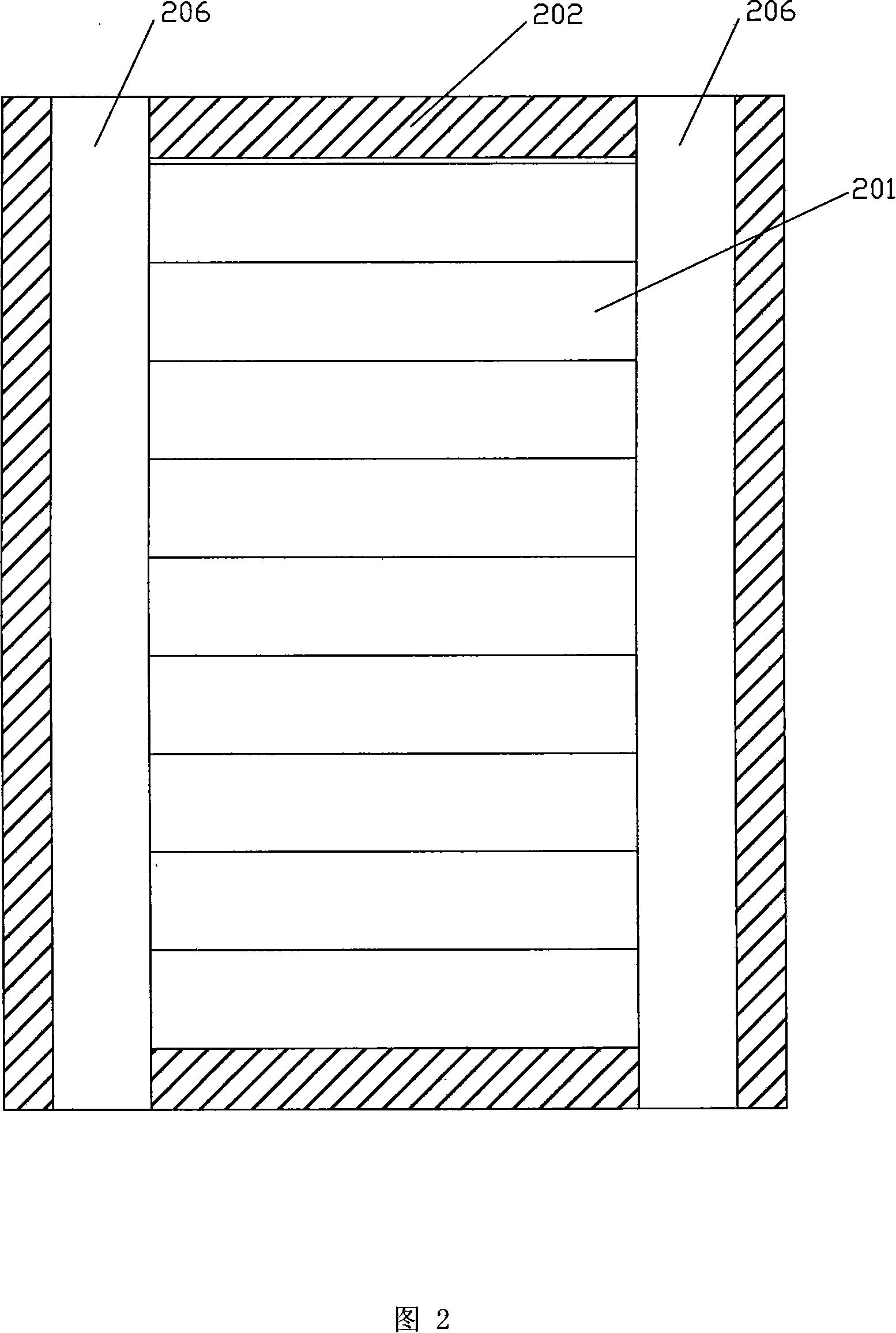
[0030] As shown in Fig. 1, it is a structural schematic diagram of the solar assembly of the present invention, and what this figure shows is the embodiment in which the double-electrode leads are drawn from the main grid line 203 of each solar battery sheet 201; Certainly, as an optional embodiment, the present invention The number of electrode leads 204 drawn from the busbar 203 of each solar cell 201 may be three or more. The solar module of the present invention includes a PCB board 202, and a plurality of solar cells 201 arranged on the PCB board 202, and the plurality of solar cells 201 are neatly arranged on the side of the PCB board 202 provid...


PUM


Abstract

The invention discloses a solar component, which includes a PCB plate and a plurality of solar cells. The solar cells are arranged on one side of the PCB plate and electrically connected with the PCB plate by contact conductors from a main grid line of each solar cell. And the number of the contact conductors from the main grid line of each solar cell is two at least. In addition, two joints are positioned between the back of the solar cells close to lateral sides and the PCB plate. One joint is a weld joint provided with pastes and the other joint is a bonding part provided with adhesives. The invention also further discloses encapsulation tools for the solar component and the encapsulation method of using the encapsulation tools to manufacture the solar component. The encapsulation tools and the encapsulation method can be used to effectively prepare the solar component with high quality, and the solar component is not disintegrable in the welding course and the multiple contact conductor guarantee the circuit security in use.

Description

technical field [0001] The invention belongs to the field of solar cells, and in particular relates to a small-sized solar module, its packaging method and a special packaging tool. Background technique [0002] With the continuous development of human beings, energy consumption is increasing, making the related technology of solar modules a hot issue of great concern to the whole society. For the solar module itself, its working life is directly related to the packaging process. In the prior art, Chinese patent CN200520069876 discloses a circuit device of a solar lamp, the device includes a solar cell, a control circuit and an LED. Wherein, the solar cell includes a plurality of cut solar cells, the solar cells are neatly arranged on one side of a PCB (printed circuit board), the control circuit is mounted on another PCB, and the above two The backs of the two PCB boards are bonded together with glue to form a lawn lamp control module that integrates solar cells and contr...

Claims


Application Information

Patent Timeline
Patent Type & Authority Applications(China)
IPC IPC(8): H01L31/042H01L31/18
CPCY02E10/50Y02P70/50
Inventor 张征宇孙宁许志伟孙剑灵
Owner BEIJING HI TECH WEALTH INVESTMENT DEV
Why Eureka
Try Eureka