
H face sectoral horn antenna including filter function

A technology of horn antenna and filter, which is applied in the microwave field, can solve the problems that metal horn antennas are not easy to be integrated on a plane, and achieve the effects of high directivity, reduced production cost, and reduced volume

Inactive Publication Date: 2011-08-24
HANGZHOU DIANZI UNIV
View PDF0 Cites 2 Cited by
  • Summary
  • Abstract
  • Description
  • Claims
  • Application Information

AI Technical Summary

Problems solved by technology

This type of antenna can well retain the highly directional and high-gain vertically polarized radiation characteristics of metal horn antennas, but it also has the disadvantage of large volume of traditional metal horn antennas and is not easy to planar integration.

Method used


Image

  • H face sectoral horn antenna including filter function
  • H face sectoral horn antenna including filter function
  • H face sectoral horn antenna including filter function

Examples


Embodiment Construction

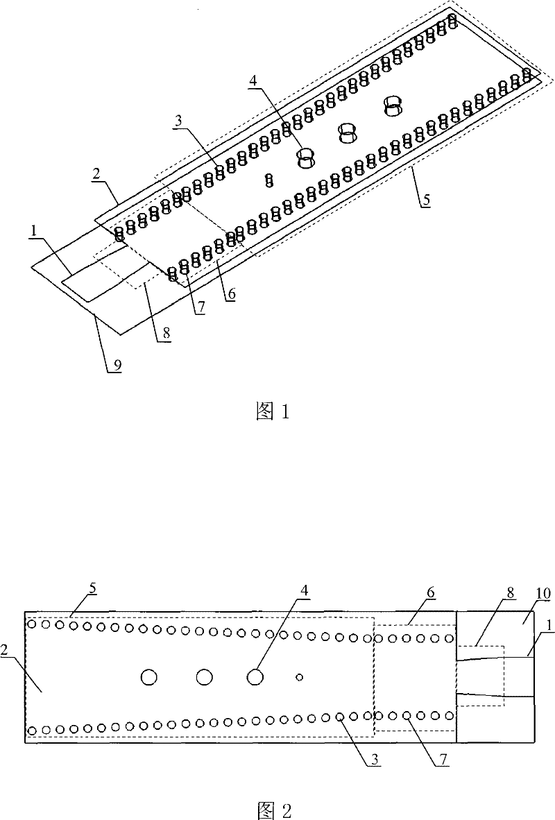
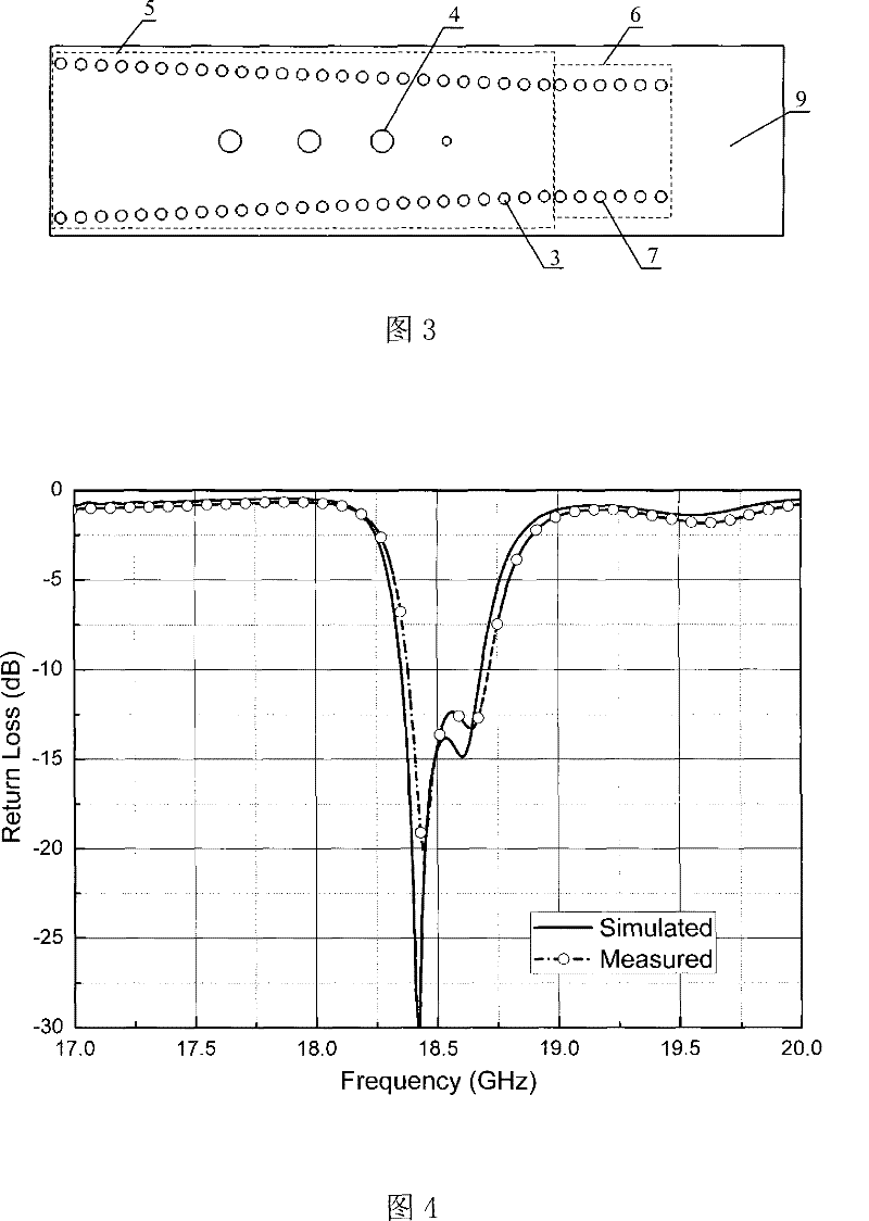
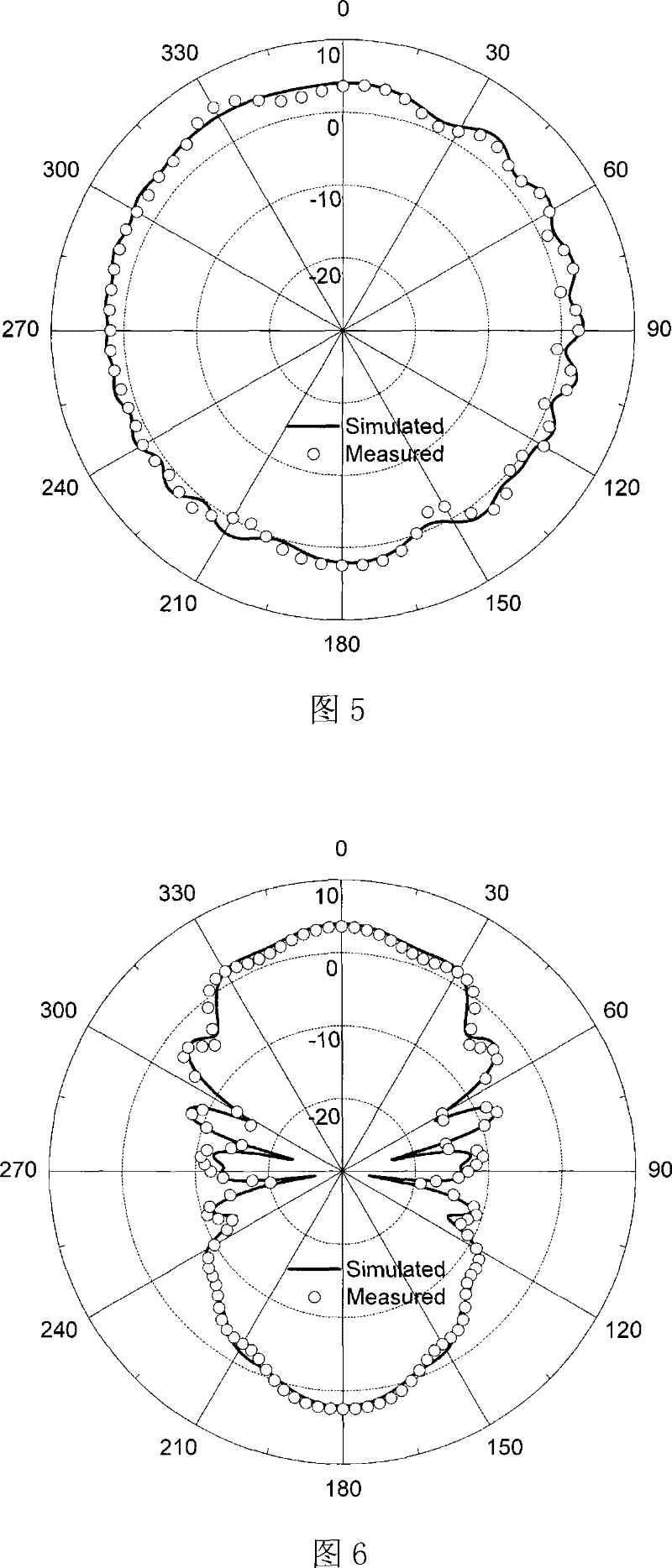
[0020] Such as figure 1 As shown, the H-face fan-shaped horn antenna including the filter function includes a Rogers5880 dielectric substrate 10 with a thickness of 1.575 mm. The two sides of the dielectric substrate 10 are coated with metal layers, which are respectively the upper metal layer 2 and the lower metal layer 9, wherein the lower metal layer Layer 9 serves as the stratum. Such as figure 2 , the upper metal layer 2 is etched with a microstrip line 1 for power feeding, and a trapezoidal converter 8 in the form of a microstrip. The output end of the ladder converter 8 is connected to the upper metal layer 2 constituting the substrate integrated waveguide, and the input end extends outward , as the microstrip line 1. The length and width of the microstrip line 1 are 6 mm and 5 mm respectively, the length of the trapezoidal converter 8 is 6 mm, and the width of the end connected to the metal layer 2 on the integrated waveguide on the substrate is 4.2 mm. Through the...


PUM


Abstract

The invention relates to an H-plane sectorial horn antenna with the function of a filter. The existing horn antenna that can not be planar integrated has a large size and a high processing cost. In the invention, a metal layer is plated at two faces of a dielectric substrate, and an upper metal layer is etched with a micro-strip line used for feeding and a micro-strip converter. A plurality of plated-through holes aligned circularly are installed by penetrating the upper metal layer, the dielectric substrate and a lower metal layer, thus forming a substrate integrated waveguide and an H-planesectorial horn. Four perturbation plated-through holes are installed by penetrating the whole substrate on the medial axis inside the opening area of the H-plane sectorial horn, used for regulating the impedance matching and forming the filtering function. The new structure adopts the substrate integrated waveguide technology, so that the function equivalent to traditional metal H-plane sectorialhorn is implemented on the normal dielectric substrate, meanwhile the filtering function of the traditional inductive post waveguide filter is successfully integrated. The dual-function integrated module is very compact in size; the whole structure can be manufactured by low cost PCB technology, and can seamlessly integrate with the system.

Description

technical field [0001] The invention belongs to the field of microwave technology, and relates to an H-plane fan-shaped horn antenna including a filter function based on a substrate integrated waveguide technology, which can be used as a radio frequency transceiver front-end antenna and applied to wireless communication occasions. As a planar antenna, it is not only a dual-function integrated module of filter and antenna, but also different from most planar antennas, it is an antenna that provides vertical polarization and can be used in some special occasions. Background technique [0002] As a standard antenna widely used in antenna testing and other occasions, the traditional metal horn antenna has the advantages of high gain, good directivity, simple structure, and easy design and manufacture. However, the shortcomings of this antenna are also obvious, such as large volume, complicated connection with subsequent circuits, and inability to integrate with the circuit plane...

Claims


Application Information

Patent Timeline
Patent Type & Authority Patents(China)
IPC IPC(8): H01Q13/00H01P1/20H01Q13/02
Inventor 罗国清孙玲玲
Owner HANGZHOU DIANZI UNIV
Learn More