
Cooling device for cutting process

A cooling device and cutting processing technology, applied in the direction of grinding/polishing safety devices, metal processing equipment, metal processing machinery parts, etc., can solve the problem of high chip disposal costs, inability to transport low-temperature gas, pollute land, water sources and air, etc. problems, to achieve the effect of lowering the temperature, saving storage and handling costs, and easy operation

Inactive Publication Date: 2008-07-02
ZHEJIANG UNIV OF TECH
View PDF0 Cites 34 Cited by
  • Summary
  • Abstract
  • Description
  • Claims
  • Application Information

AI Technical Summary

Problems solved by technology

(2) If the cutting fluid is discharged without treatment, it will pollute the environment, pollute the land, water and air
(3) The supply and management cost of cutting fluid, especially the cost of toxic and harmful cutting fluid and chip disposal with cutting fluid is quite high, which greatly increases the production cost
(4) Additives (such as S, Cl) in cutting fluid will cause potential quality accidents of parts, such as intergranular corrosion, etc.
[0003] The use of low-temperature gas instead of cutting fluid can effectively solve the problem of cutting heat in the cutting process without causing pollution, but ordinary devices for delivering cutting fluid cannot meet the needs of delivering low-temperature gas

Method used


Image

  • Cooling device for cutting process
  • Cooling device for cutting process
  • Cooling device for cutting process

Examples


Embodiment Construction

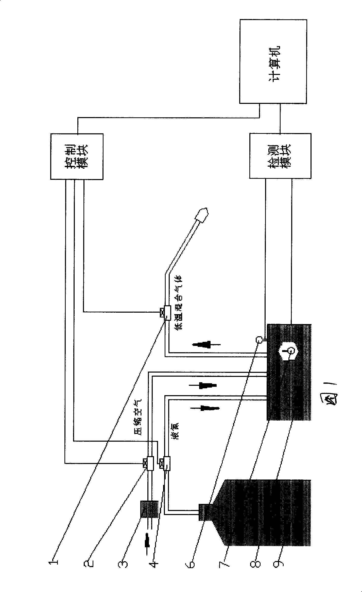
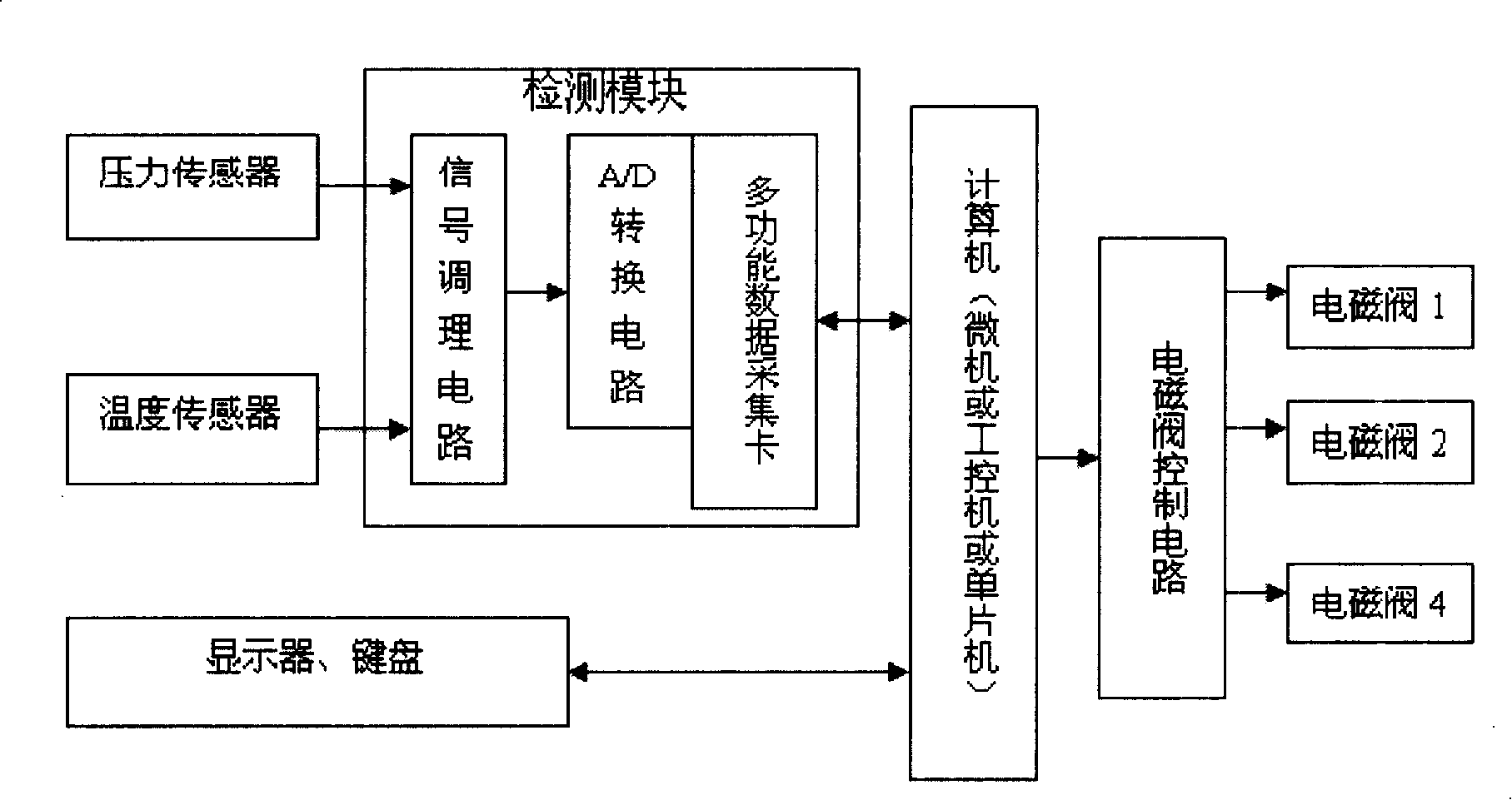
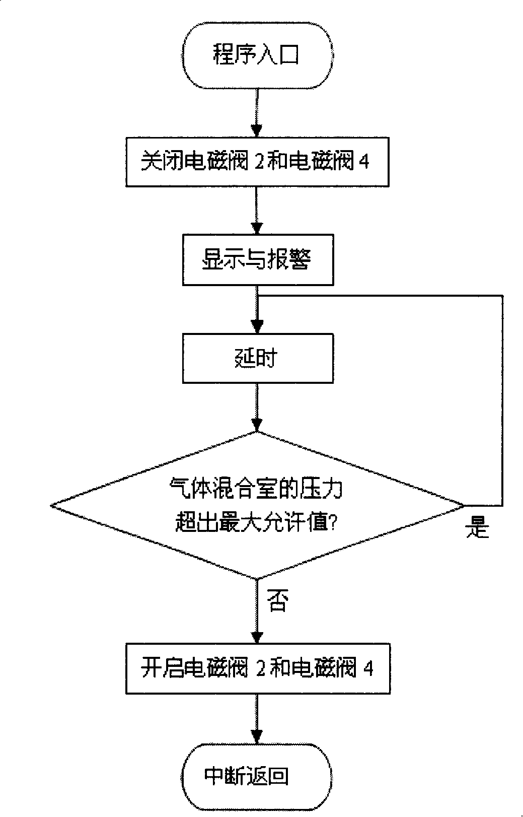
[0014] The cutting cooling device of the present invention includes a cryogenic liquid storage tank 9, a gas mixing chamber 8, a compressed air filter 3, a pipe joint, a liquid nitrogen delivery pipe, solenoid valves 1, 2, 4, a pressure sensor 6, and a temperature sensor 7. Control module, detection module, computer (industrial personal computer, microcomputer or single-chip microcomputer), display, keyboard, signal line, low-temperature liquid storage tank 9 is connected to gas mixing chamber 8 through gas delivery pipe and electromagnetic valve 4, and compressed air passes through gas delivery pipe Connect the gas mixing chamber 8 through the filter 3 and the electromagnetic valve 2, and the low-temperature gas and the normal temperature gas are mixed in the mixing chamber, and the output of the gas mixing chamber 8 passes through the gas delivery pipe and the electromagnetic valve 1; the temperature sensor 7 and the The pressure sensor 6 is connected with the detection modul...


PUM


Abstract

The invention provides a cutting processing cooling device, comprising a low-temperature liquid storage tank 9, a gas mixing room 8, a compressed air filter 3, a pipe joint, a liquid nitrogen conveying pipe, electromagnetic valves 1, 2, 4, a pressure sensor 6, a temperature sensor 7, a control module, a detection module, a computer (industrial computer, micro-computer or singlechip), a display, a keyboard, and a signal line. The low-temperature liquid storage tank 9 is connected with the gas mixing room 8 through a gas conveying pipe and the electromagnetic valve 4; the compressed air is connected with the gas mixing room 8 through the gas conveying pipe, the filter 3 and the electromagnetic valve 2; the low-temperature gas and the normal-temperature gas are mixed in the mixing room; the output of the gas mixing room 8 passes through the gas conveying pipe and the electromagnetic valve 1; the temperature sensor 7 and the pressure sensor 6 in the gas mixing room 8 are connected with the detection module through the signal line; the electromagnetic valve 1, the electromagnetic valve 2 and the electromagnetic valve 4 are connected with the control module through the control signal line; the control module and the detection module are connected with the computer through communication lines.

Description

technical field [0001] The invention is a pollution-free cutting processing cooling device based on the concept of green manufacturing, which can be applied to cutting processing such as turning, drilling, milling and grinding in industrial production. Background technique [0002] With the popularization of numerical control and the improvement of cutting tool manufacturing technology, the processing efficiency of metal cutting machine tools is getting higher and higher, and the resulting cutting heat and tool tip temperature rise are also getting faster and higher. The amount used is also increasing, and its proportion in the processing cost is also increasing, even reaching 15%, which makes the processing cost of mechanical parts gradually increase; in the early 1990s, developed countries focused on metal processing. The impact of the environment has been carefully discussed, and it is pointed out that cutting fluid is a pollution source in the cutting processing industry...

Claims


Application Information

Patent Timeline
Patent Type & Authority Applications(China)
IPC IPC(8): B23Q11/10B24B55/02G05D27/02F17D1/02F17C7/04
Inventor 王秋成张召明王益嗣
Owner ZHEJIANG UNIV OF TECH
Learn More