
Flue gas denitrating technique with preposed whirlwind beforehand dust removal SCR

A technology of pre-dusting and SCR reactor, applied in the field of flue gas denitration process, can solve the problems of air pre-cleaner contamination, increased operating costs, large losses, etc., to reduce the size and quantity of electric fields, improve quality and utilization, blockage the effect of decreasing the probability of

Active Publication Date: 2010-06-16
CPI YUANDA ENVIRONMENTAL PROTECTION ENG +1
View PDF4 Cites 0 Cited by
  • Summary
  • Abstract
  • Description
  • Claims
  • Application Information

AI Technical Summary

Problems solved by technology

[0003] Due to the high concentration of flue gas dust in the SCR reactor, the fly ash contained in it is easy to cause catalyst wear and poisoning, shorten the service life of the catalyst, and increase the operating cost; among them, the large particle fly ash (especially popcorn fly ash) is particularly It is easy to cause catalyst clogging. In order to reduce the probability of catalyst clogging, it is generally necessary to choose a catalyst with a large pore size, which will result in a larger catalyst volume and increase the investment cost of the SCR project. If the catalyst is clogged, the furnace must be shut down, and the loss is huge. Therefore, it is often necessary to set up an SCR bypass 6 in the system design, which will further increase the investment cost of SCR denitrification; in addition, due to the high concentration of fly ash, the leakage of NH from the denitrification reaction 3 with SO 3 and H 2 O will generate substances such as ammonium bisulfate (ABS), which has a relatively high viscosity, and will cause dust to accumulate on the surface of the air preheater, causing contamination and corrosion of the air preheater, and blockage of the air preheater 4. Therefore, it is necessary to increase the cleaning frequency of the air preheater 4
[0004] In addition, in the traditional process, due to the wear and tear of the denitrification catalyst, the heavy metals of the worn denitrification catalyst will be enriched in the dust of the electrostatic precipitator 5, resulting in a high concentration of heavy metals in the fly ash of the electrostatic precipitator, which will affect the application of fly ash in power plants
[0005] The current trend is to cancel the SCR bypass 6, which will undoubtedly further increase the risk of downtime due to fly ash clogging, and the traditional SCR process will be more severely challenged

Method used


Image

  • Flue gas denitrating technique with preposed whirlwind beforehand dust removal SCR
  • Flue gas denitrating technique with preposed whirlwind beforehand dust removal SCR
  • Flue gas denitrating technique with preposed whirlwind beforehand dust removal SCR

Examples


Embodiment Construction

[0027] Taking 1×660MW coal-fired unit as an example, the present invention will be further described in conjunction with the accompanying drawings and embodiments.

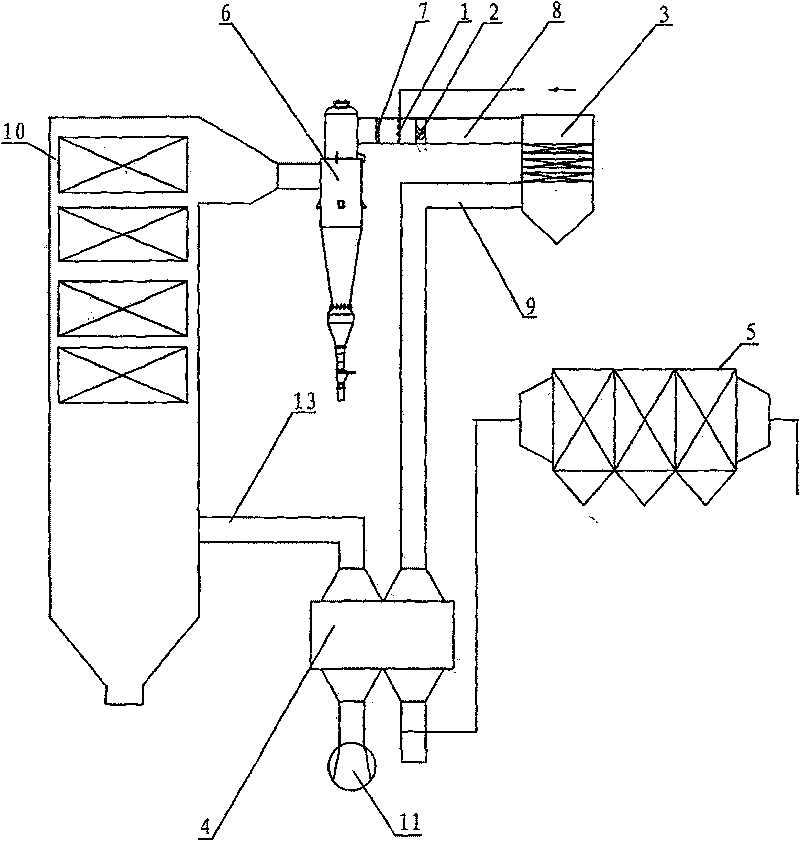
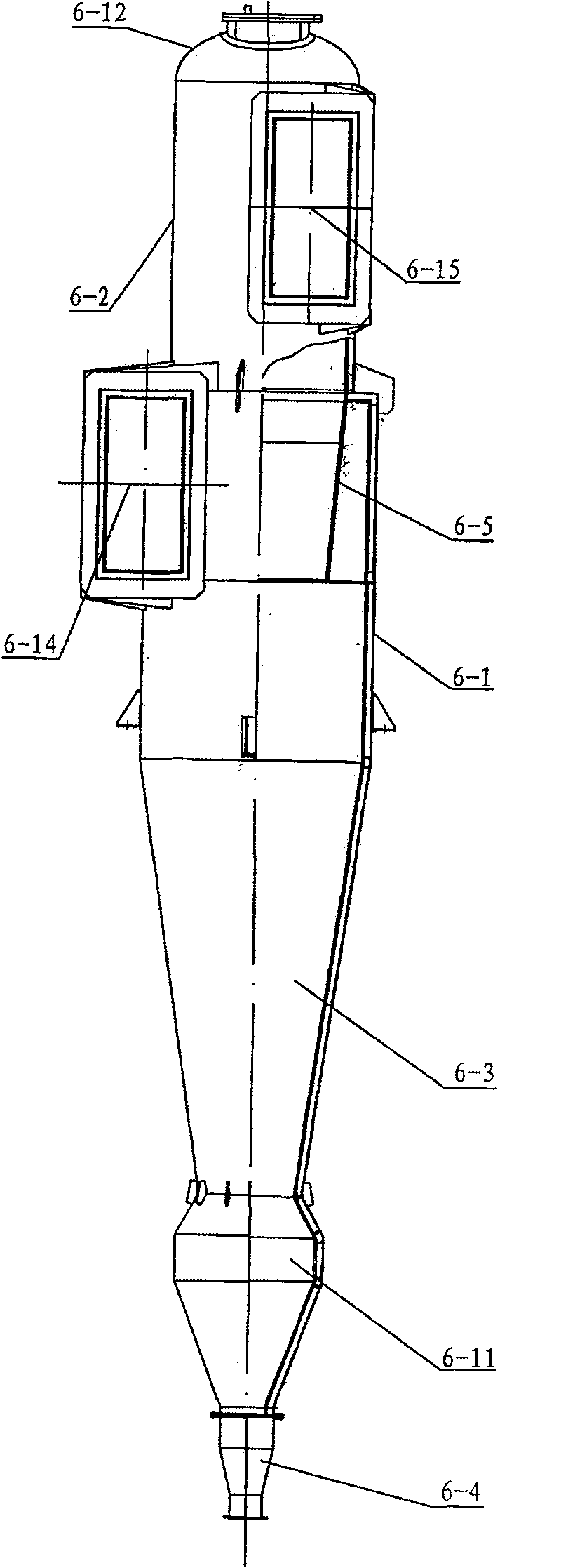
[0028]Step 1, the flue gas from the outlet of the boiler 10 is directly connected with the high temperature resistant cyclone separator 6 through the flue. The flue gas flow rate in this part is 1.77 million Nm3 / h, the flue gas temperature is 384°C, the concentration of some flue gas components is NOx400mg / Nm3, SO2 3252mg / Nm3, and dust 24g / Nm3. The flue gas at the outlet of the economizer enters the cyclone separator through the volute flue gas inlet 6-14, and the flue gas passes through the centrifugal action of the cyclone separator, and most of the fly ash with large particle size (including popcorn fly ash) is removed. The flue gas is discharged through the tangentially extended flue gas outlet 6-15, and enters the flue gas inlet pipe 8, and the separated fly ash is periodically discharged by regularly opening...


PUM


Abstract

The invention discloses a preposing cyclone pre-dedusting SCR flue gas denitration technique. The flue gas extracted from a boiler economizer (12) primarily passes through a high temperature resistantcyclone separator (6), then passes through a flue gas current equalizer (7) and a static mixer (2) to unify the flow direction of the flue gas evenly; meanwhile, the flue gas after being mixed evenlywith ammonia is preprocessed before reacting with a catalyst of an SCR reactor (3); finally, the flue gas is output after the temperature is reduced through an air preheater (4) and the flue gas is dedusted through an electrical precipitator (5). The invention reduces the volume of the catalyst and the SCR reactor, reduces the requirements of the support, eliminates an SCR bypass and greatly reduces engineering cost of the SCR; meanwhile, the invention also prolongs the service life of the catalyst and the cleaning period of the air preheater without installing a soot blower or prolonging theperiod of sootblowing.

Description

technical field [0001] The invention belongs to a flue gas denitrification process, in particular to a pre-cyclone pre-dust removal SCR flue gas denitrification process. Background technique [0002] Traditional flue gas denitrification devices such as Figure 5 As shown, the upper part of the SCR reactor 3 is connected to the flue gas inlet pipe 8 drawn from the boiler 10, and the flue gas inlet pipe 8 is provided with a static mixer 2, and the front of the static mixer 2 is provided with an ammonia injection grid 1, so The bottom of the SCR reactor 3 is connected to the electrostatic precipitator 5 through the flue gas output pipe 9, and the flue gas output pipe 9 between the electrostatic precipitator 5 and the SCR reactor 3 is provided with an air preheater 4, and the boiler 10 The air input pipe 13 is connected to the boiler 10 through the air preheater 4 through the fan 11 , and the nozzle of the ammonia injection grid 1 faces the SCR reactor 3 . Baffles 12 are respec...

Claims


Application Information

Patent Timeline
Patent Type & Authority Patents(China)
IPC IPC(8): B01D53/56
Inventor 杜云贵李锋刘清才董凌燕尹正明洪燕隋建才余宇王方群杨剑吴其荣邓佳佳
Owner CPI YUANDA ENVIRONMENTAL PROTECTION ENG
Learn More