Micro-electrolysis device for aeration fluidized bed

A fluidized bed and micro-electrolysis technology, applied in the direction of electrochemical water/sewage treatment, can solve the problems of large power consumption and easy loss of packing, and achieve the effect of reducing operating costs, avoiding packing loss, and reducing electricity consumption.

Inactive Publication Date: 2008-07-16
无锡市林信环保工程有限公司
View PDF0 Cites 28 Cited by
  • Summary
  • Abstract
  • Description
  • Claims
  • Application Information

AI Technical Summary

Problems solved by technology

Although the fluidized bed solves the problem of agglomeration, in order to ensure the fluidized state, the

Method used


Image

  • Micro-electrolysis device for aeration fluidized bed

Examples


Embodiment 1

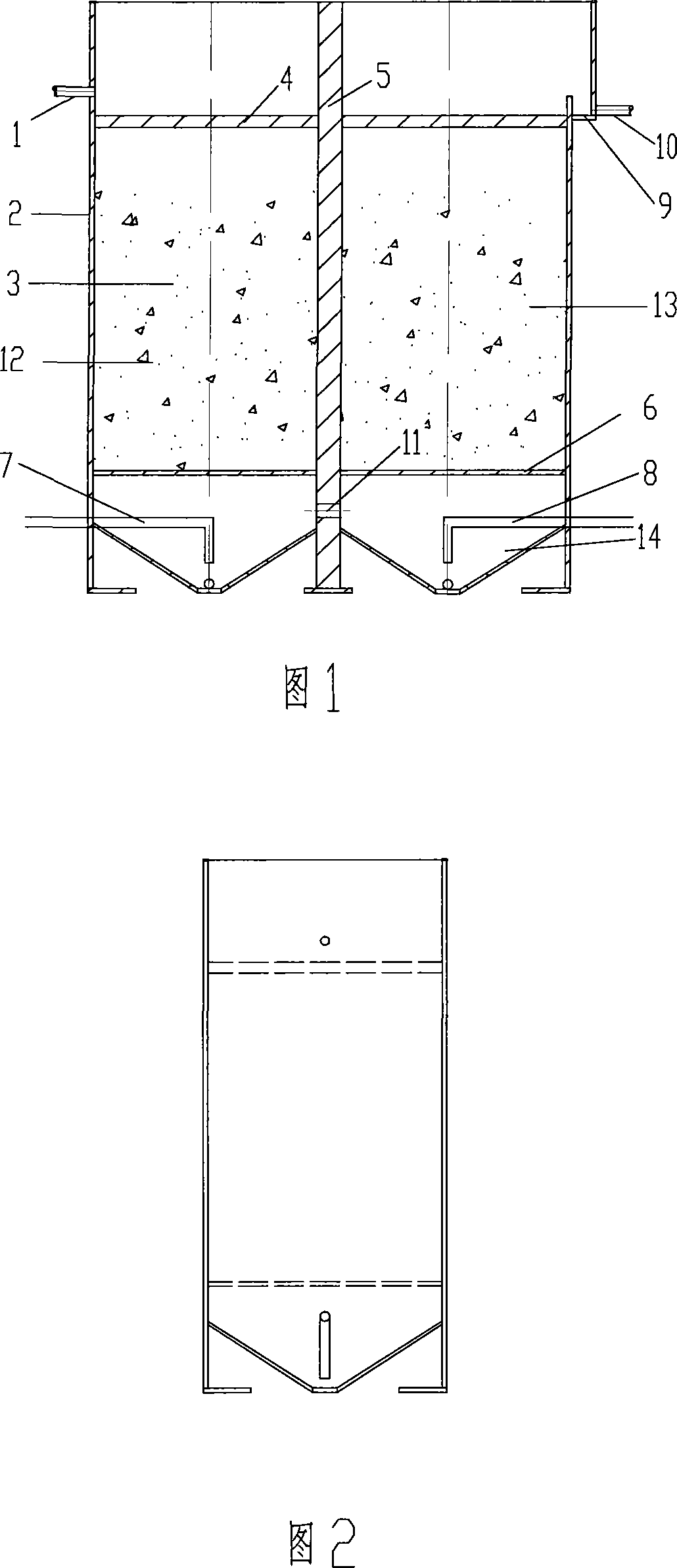
[0018] Put LXFC series iron-carbon filler in the micro-electrolysis device with a height of 1.25 meters made of PVC material, and introduce a certain benzene-containing organic wastewater into the water inlet pipe 1 of the aeration fluidized bed micro-electrolysis device. Waste water quality: COD Cr =1000-1500mg / L, PH=6-7, BOD / CODCr Cr =0.50, the organic matter is degraded obviously, and the biodegradability of the waste water is improved.

Embodiment 2

[0020] The device in Example 1 is used to treat printing and dyeing wastewater, and the wastewater is introduced into the water inlet pipe 1 of the aeration fluidized bed micro-electrolysis device, and the wastewater passes through the grid 4 through the filler 3, and an electrochemical reaction occurs, accompanied by reduction degradation and coagulation, etc. physical and chemical phenomena. The aeration tube 7 is used to continuously impact the bucket bottom of the first chamber 12, and the second chamber is not aerated, so that the filling in the first chamber is in a fluidized state and reacts. The water after the reaction in the first chamber 12 enters the second chamber 13 through the hole 11 at the bottom of the partition plate 5, and further micro-electrolysis reaction occurs. The reacted water passes through the outlet weir 9 and is discharged from the outlet pipe 10. The COD of the wastewater Cr 800-1500mg / L, PH=8-11, chromaticity 264-1100 (dilution factor), after b...


PUM


Abstract

The invention discloses a device for treating micro-electrolytic water. The invention, provides a micro-electrolyzing device by a fluidized bed, which has little filler consumption under an acid condition, little deposit generated in a subsequent neutralizing stage, non-block in a filler layer and little power consumption. The device comprises a bed body, an inlet pipe on a side where the bed body is close to an upper end, an outlet pipe on a side where the bed body is close to the upper end and is opposite to the inlet pipe, a porous support plate on a bottom of the filler in the bed body and an effluent weir on which top of the bed body is close to the outlet pipe. A clapboard is arranged in the middle of the bed body to divide the interior part of the bed body into two cavities, which are arranged as funnel structures respectively; two high-pressure tracheas are let in the bottom of the two cavities inside the bed body through outside the bed body respectively. The device allows the fine particle subsided at the bottom of the funnel in a fluidized state without soil hardening and can further generate micro-electrolysis reaction with the waste water, which at the same time reduces power consumption; the grate prevents impurity such as fiber to enter the device and avoids the filler loss.

Description

technical field [0001] The invention relates to a micro-electrolysis water treatment device. Background technique [0002] The micro-electrolysis method is a good process for treating wastewater by using the principle of metal corrosion to form a primary battery, also known as the internal electrolysis method and iron filings filtration method. Because this method has the advantages of wide application range, good treatment effect, long service life, low cost and convenient operation and maintenance, and can use scrap iron scraps as raw materials, and does not need to consume power resources, it has the characteristics of "treating waste with waste". significance. At present, the micro-electrolysis method has been successfully applied to the treatment of wastewater such as dyes, printing and dyeing, heavy metals, pesticides, pharmaceuticals, and oil. Some problems have been exposed during the operation of the existing micro-electrolysis treatment device. After a period of ...

Claims


Application Information

Patent Timeline
IPC IPC(8): C02F1/46
Inventor 王开林陈前荣陈敏
Owner 无锡市林信环保工程有限公司
Why Eureka
Try Eureka