Bidirectional mobile full duplex wireless optical communication system

A wireless optical communication, two-way motion technology, applied in transmission systems, electromagnetic wave transmission systems, electromagnetic transceivers, etc., can solve problems such as affecting the alignment of the transmitting end and the receiving end, difficult receiving points to receive correctly, and large impact on transmission quality. , to achieve the effect of not easy electromagnetic interference, low cost and strong anti-interference ability

Inactive Publication Date: 2008-08-06
SHANGHAI UNIV +1
View PDF0 Cites 2 Cited by
  • Summary
  • Abstract
  • Description
  • Claims
  • Application Information

AI Technical Summary

Problems solved by technology

[0003] Although FSO has many advantages, there are also some problems that cannot be ignored: 1. FSO is a line-of-sight broadband communication technology. When the transmission exceeds a certain distance, the beam will become wider, making it difficult for the receiving point to receive it correctly, causing communication signal distortion. Interruption; 2. Weather effects, rain, snow, fog have a greater impact on the transmission quality; 3. Object blocking and shaking will affect the alignment between the transmitting end and the receiving end; 4. Lasers exceeding a certain power may be harmful to people Eyes are affected, so the laser power must meet eye safety standards
However, when one end shakes or moves relative to each other, the data transmission will be greatly affected, and complex tracking and control devices are required to align the laser beams at both ends, which increases the complexity of the equipment and makes it difficult to carry out maintain
In some occasions of field application (such as the monitoring of loading and unloading status of large-scale port containers), the wireless optical communication equipment often moves in a straight line with the mechanical equipment. At this time, the wireless optical communication system with both ends fixed and stationary cannot meet the requirements

Method used


Image

  • Bidirectional mobile full duplex wireless optical communication system

Examples


Embodiment Construction

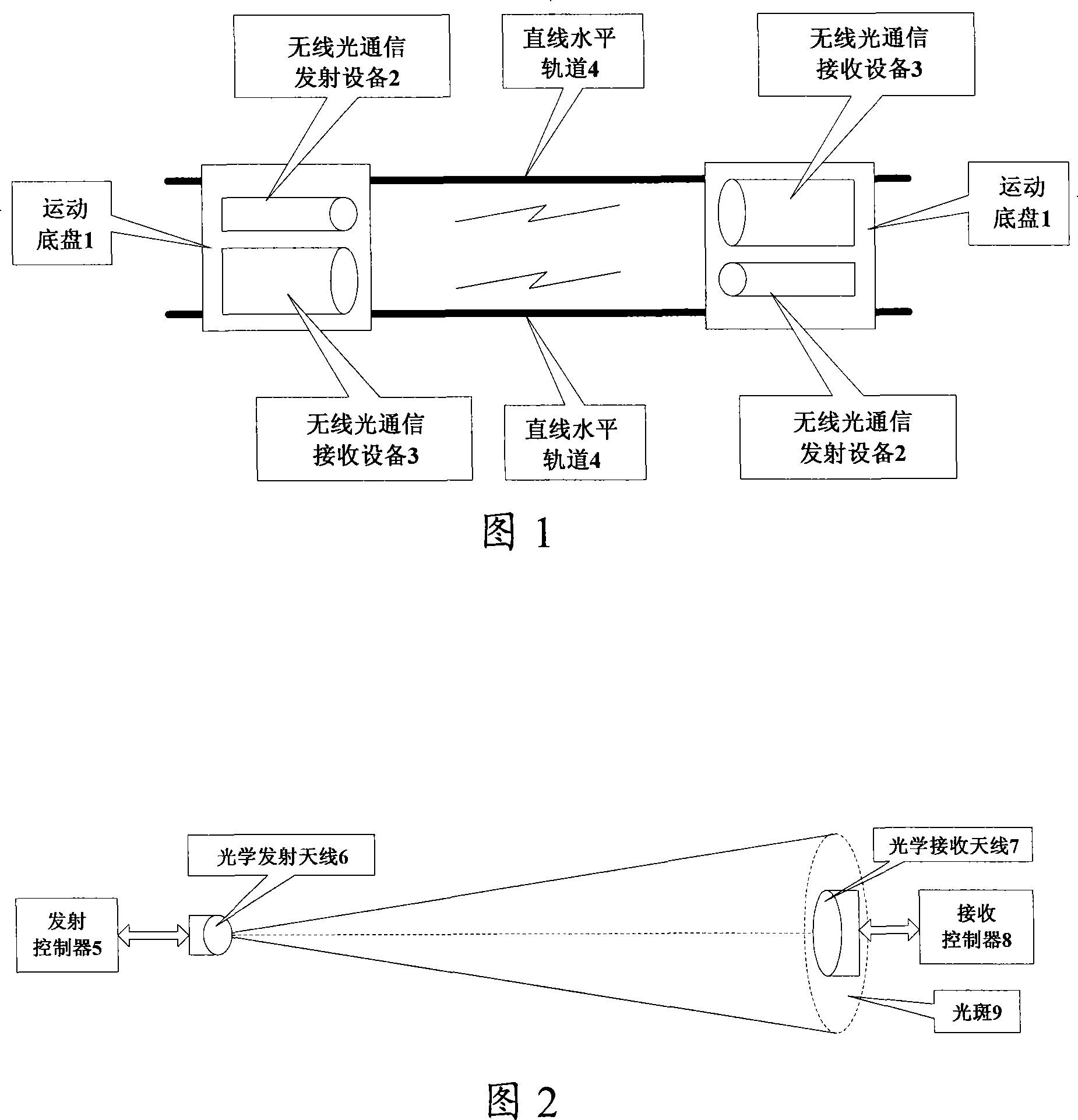
[0013] A preferred embodiment of the present invention is described as follows in conjunction with accompanying drawing:

[0014] Referring to FIG. 2 , the moving chassis 1 performs bidirectional reciprocating motion on the horizontal linear track 4 , and the wireless optical communication transmitting device 2 and the wireless optical communication receiving device 3 are respectively installed on the two moving chassis 1 . Each mobile chassis 1 has a wireless optical communication transmitting device 2 and a wireless optical communication receiving device 3, and the transmitting controller 5 inside the wireless optical communication transmitting device 2 communicates with the receiving controller 8 inside the wireless optical communication receiving device 3. Communication, control the forward, backward, acceleration, deceleration and other states of the sports chassis 1. In field applications, using cables or optical cables for data communication is easy to wear out the cabl...


PUM


Abstract

The invention relates to a bidirectional movement type full duplex wireless optical communication system which comprises wireless optical communication transmission equipment and wireless optical communication reception equipment, wherein, two mobile ground disks are movably configured on horizontal linear rails and are both fixed with the wireless optical communication transmission equipment and the wireless optical communication reception equipment. The invention can establish a movement type full duplex wireless optical communication system on the linear horizontal rails to realize the high-speed wireless optical communication of data transmission. Compared with the prior static type wireless optical communication system, the bidirectional movement type full duplex wireless optical communication system has a simple structure, strong anti-jamming ability, high sensitivity, easy manufacture and low cost, does not need complicated dynamic tracing, and is applicable to the continuous real-time data transmission with different distances in the linear movement state.

Description

Technical field: [0001] The invention relates to a two-way motion full-duplex wireless optical communication system, which is used for high-speed data transmission between moving equipment on a straight and horizontal track, and belongs to the field of optical fiber communication. Background technique: [0002] Wireless optical communication is also called free space optical communication (Free Space Optics, FSO for short), also known as infinite laser communication. Compared with microwave communication, wireless optical communication uses the atmosphere as the transmission medium, avoiding expensive fiber laying and maintenance work; no need to apply for a frequency license; high data transmission rate, large information capacity; good electromagnetic compatibility, strong anti-electromagnetic interference ability ; Low cost, simple construction. It is precisely because of these advantages that it has become a new broadband wireless access technology and has attracted wid...

Claims


Application Information

Patent Timeline
Patent Type & Authority Applications(China)
IPC IPC(8): H04B10/10H04B10/04H04B10/06H04B10/40
Inventor 王廷云付兴虎王建飞俞起帆庞拂飞王硕峰郭强宋英雄李迎春张嘉毅陈振宜陈健汪敏
Owner SHANGHAI UNIV
Why Eureka
Try Eureka